Siction 12, Installing ilictrical wiring, Fiction 13 – Bard Bayrd Furnace 403293A User Manual
Page 21: Following field wiring diagram, Field wiring diagram figure 21, Installing electrical wiring, Following field wiring diagrams, Adjusting room thermostat heat anticipator
Attention! The text in this document has been recognized automatically. To view the original document, you can use the "Original mode".
a.
Use 9/64" Hex Allen wrench to remove tour
screws. Check that O-ring is in bottom of gas
inlet elbow. Rotate elbow to desired position.
b.
Alternately tighten tour screws to 45 inch pounds
to form a gas tight seal.
c.
Use a commercial soap solution made to detect
leaks and check all gas piping connections.
Bubbles indicate gas leakage. Seal all leaks be
fore proceeding.
WARNINOi
Never use an open flame to
check for gas leaks. If a leak does exist, a
fire or explosion could occur, resulting In
damage, Injury or death.
3.
Allowing tor Electronic Air Cleaners.
Some large electronic air cleaners will interfere with
incoming gas line. Install air cleaner on opposite fur
nace side from gas entry or route gas pipe over top
of air cleaner through one of alternate knockouts.
SICTION 12 —
INSTALLING ILICTRICAL WIRING.
Equipment Needed: Save time by getting these tools before
you start: Item number(s) 2 listed in Section 10.
Select a location for room thermostat that is away from sup
ply and return air registers, on draft-free interior wall, and not
near lights, television, direct sunlight, or other heat sources.
Install thermostat following field wiring diagram in Section
13. Use electrical wiring that meets current National Electrical
Code ANSI/NFPA 70 and local codes. Use Type T (63 de
grees C rise) wire or equivalent. See Section 30 for code
information.
WARNINGi
Provide furnace with ita own separate elec
trical circuit, means of circuit protection and electrical
disconnect switch. Follow current National Electrical Code
ANSI/NFPA 70 and state and local codes. Failure to pro
vide these shut-off means could cause electrical shock
or fire, resulting In damage, Injury or death.
install proper electrical grounding by attaching grounding
source to green wire conductor in furnace junction box. Fol
low current National Electrical Code ANSI/NFPA 70 and local
codes.
WARNINGS
Furnace must have proper electrical ground.
Failure to provide a proper electrical ground could cause
electrical shock or fire, resulting In damage. Injury or
death.
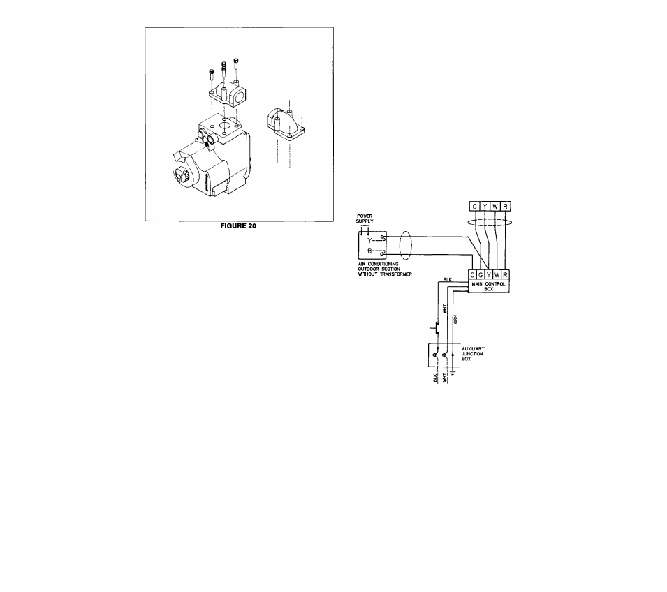
fICTION 13 —
FOLLOWING FIELD WIRING DIAGRAM
HEATING COOUNG
THERMOSTAT MODEL
TO 115V 1 PH 60 H2
POWR SUPPLY PER
LOCAL CODES
FIELD WIRING DIAGRAM
FIGURE 21
NOTE: When replacing original wire, use same type, color,
or equivalent wire. Remember to renumber wire ends.
SECTION 14 — ADJUSTING ROOM
THERMOSTAT HEAT ANTICIPATOR
Equipment Needed: Save time by getting these tools before
you start: Item number(s)5,17 and 18 listed in Section 10.
Wire system using field wiring diagram in Section 13.
19