Warning, D. pilot – Bryant 396G User Manual
Page 8
Attention! The text in this document has been recognized automatically. To view the original document, you can use the "Original mode".
4. Remove draft diverter. Screws are located inside draft
diverter opening.
5. Remove flue baffles from flue outlets of heat exchanger.
6. Remove secondary air shield and burners. To remove
pilot burner, disconnect pilot supply tube (and ther
mocouple on 100% shut-off models) at gas valve.
7. Clean flue ways with brush and or vacuum. Check heat
exchanger for leaks and cracks. Replace if necessary.
8. Replace flue baffles. Be sure all screws are in place and
tight.
9. Replace draft diverter and vent connector. Be sure
screws are replaced and tight.
10. Replace burners and secondary air shield.
11. Turn on gas and electricity. Check for gas leaks.
WARNING:
N«-vi>r u.«i' a rn.ilch or other of)«'n flame Ifi check
for gas leaks. Use a soap-and-water solution.
D. Pilot
Check the pilot and clean if necessary at the beginning of
each heating season. The pilot flame should be high enough
for proper impingement of the safety element and to light
the burners. Remove the accumulation of soot and carbon
from the thermocouple safety element or sensing probe.
E. Electrical Controls and Wiring
NOTE:
There may be more than one electrical supply to
unit.
With power disconnected to unit, check all electrical connec
tions for tightness. Tighten all screws on electrical connec
tions. If any smoky or burned connections are noticed, dis
assemble the connection, clean all parts and stripped wire,
and reassemble properly and securely. Electrical controls
are difficult to check without proper instrumentation; there
fore, reconnect electrical power to unit and observe unit
through one complete operating cycle. If there are any dis
crepancies in the operating cycle, contact your Dealer and
request service.
^_L
16
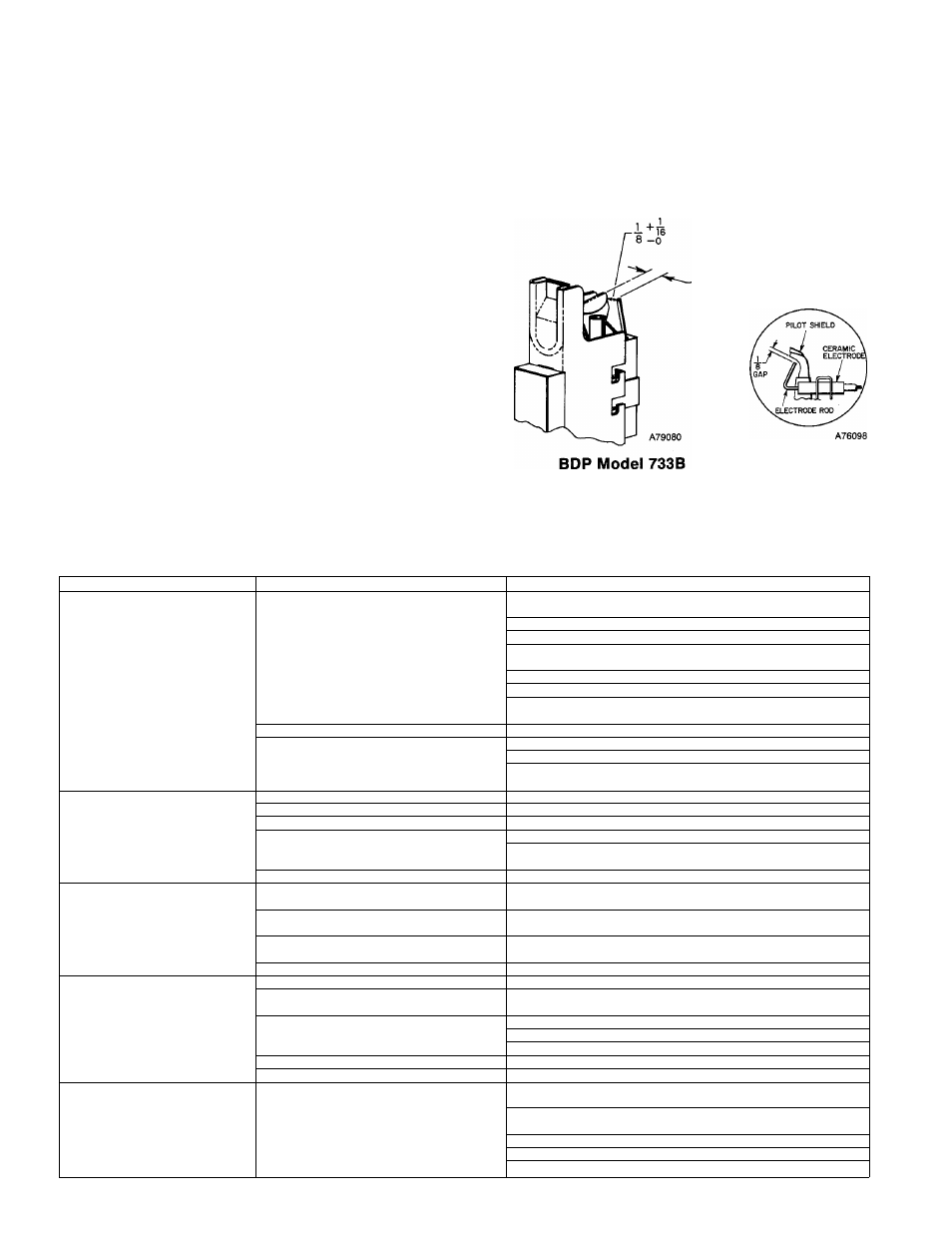
Penn Model J996
Figure 18 — Position of Electrode to Pilot
TABLE VII-TROUBLE ANALYSIS CHART
WARNING: Turn off gas and power supply to unit before servicing
(unless specific test requires gas and electric supplies).
SYMPTOM
CAUSE
REMEDY
Pilot will not light.
No spark at electrode
Readjust, if necessary, so that
gap between electrode tip and pilot burner is as shown in Figure 18.
Clean dirt or moisture accumulation from electrode ceramic with cloth.
Cracked ceramic—replace pilot electrode assy.
Check for loose or broken wiring at and between spark generator and
electrode. Replace wire or tighten connection as necessary.
Check fuse or cl rcuit breaker for 115-volt supply to furnace.
Check blower access panel for proper installation.
Check 24-volt input to spark generator. If you read 24 volts and above
steps have been completed, replace spark generator assy.
Spark shorting out to main burner
Readjust electrode as specified.
No gas at pilot burner
Clean pilot orifice.
Check voltage to terminals 3 and 5 or TR and TH of gas valve.
Check for proper opening of pilot valve, broken wires, or loose
connections. If no deficiency is found, replace valve assy.
Burners will not ignite.
No 115-volt power to furnace
Connect to power supply. Check fuse, wiring, or circuit breaker.
No 24-volt power to control circuit
Replace transformer.
Miswired or loose connections
Check all wiring and all wirenut connections.
No gas at main burners
Check voltage to terminals 1 and 2 or TR and TH of gas valve.
Check for proper opening of main gas valve, broken wires, or loose
connections. If no deficiency is found, replace gas valve assy.
Dirty pilot—yellow flame
Clean pilot orifice.
Blower operates continuously.
Thermostat fan switch
in ON position
Move thermostat fan switch to AUTO position.
Fusible link blown
Correct combustion air and venting practice—replace fuse link
with identical part.
Dirty filter causing
limit operation
Clean dirty airfilter-reinstall.
Defective heat relay
Replace printed-circuit board.
Inadequate heating
Furnace undersized for application
Replace with proper size furnace.
Gas input to furnace too low
Check gas pressure at manifold. Clock gas meter for input. If too low,
increase manifold pressure or install correct orifices.
Limit switch cycles main burners
Clean dirty air filter—reinstall.
Increase blower speed.
Open registers—ductwork restricted.
Manual reset limit switch contacts open
Blower motor failure—replace motor.
Thermostat anticipator set too low
Check thermostat circuit amps and set anticipator accordingly.
Aldehyde odors, (CO),
sooting flame-
floating flame
Incomplete combustion-
poor flame characteristics
Adjust air shutter on burners to provide soft, blue, flame. Check all
screws around flue outlets and burner compartment. Tighten.
See “Section II, Location & Air for Combustion & Ventilation” (Std
Procedures for Gas-Fired Furnaces).
Replace cracked heat exchanger.
Reduce input and check orifices—furnace overfired.
Check vent for restriction.
-
8
-