Table v — pilot gas gonsumptló^j – Bryant 396G User Manual
Page 5
Attention! The text in this document has been recognized automatically. To view the original document, you can use the "Original mode".
Whén thè pilot flame is established, pilot 6ÌÌ switches iiè
contacts in approximately 40 to 60 secohcis, energizing thè
main valve portion of gas valve 5F and deenergizing pilot
igniter 6F and the “pick” coil portion of the pilot solenoid in
gas valve 5F.
The main valve poirtibii of gas valve 5F is heat motor operated;
therefore, after approximately 10 seconds, (Robertshaw Valve
opens instantly), this portion of the valve opens, permitting
gas flow to the main burners where the gas in ignited by pilot
6H.
2. BDP 647 and Essex 242 iSas Valves
(Match-Lit Models)
The furnace pilot must bè lit. to energize the thermal
magnet circuit of gas valve 5E; thus permitting gas flow tb
thè remaining portion of the valve.
tABlE V — PILOT GAS GONSUMPTlÓ^J
......... Pilot
Gas
BtüH
In; wc
ËDP 733B
...... Nat
........ 875
.......... 5;0
Penri
Nat
1250
3.5
Penn
Prop.
690
10.5
Wheii thé thermostat “calls for heat;” the control circuit is
closed bet\veeh terminals R and W, Power froni transformer
ÍÁ through fusible link Í1C and limit sw;itches 7H1/7H2
energizes gas valve 5É, causing the valve tb Open ând per
mitting gas flow to thé main burners, wherè it is ignited bÿ
the pilot. Some furnaces af e equipped with a step opening gab
valve. When the burners first i^ite, the flame will be low and
soft. In approximately 15 seconds the valve will fully open and
the burner uamé will be normal size.
3. Essex 242 Gas Valve (HD Models) LPG
When the thermostat "calls for heat,” the control circuit is
closed betwëèü terminals R ând W. Power from transfofniër
l ihrotigh Rigibiê lüik íiC, limit switches 7HÍ & 7ÍÍÍ, âhd
through lockout tifhëf ínbdüle 6CÍ3, ëhergièës pilot igniter 8CÍ2
and the pilot valve part of gas valve 5F, causing the valve to
Open and to ignite the pilot. When the pilot flame is estab
lished, thë pilot Sensing probe energizes the main gas valve,
permitting gas flow, to thè main burners. The pilot electrode
continues sparking for approximately 5 to 10 seconds after the
pilot flame has beeii established.
If the pilot flamè iS not proven withiii approximately 30
seconds; lockout module 6G3 opens, deenèrgizing gaS valve 5F
and stopping thé gas flo\v to thë pilot; The. lockout module
remains Open until it is manually reset bÿ interrupting thé
low-voltagé or high-voltage circuit for approximately 30
Seconds.
3. Blower Circuit
With power through thé solid-state time-delay circuit on
printed-circuit board 6C1 and heat relay 2A; blower motor
3
d
is energized on heating speed approximately 75 seconds
after gas valve 5E has been energized (or the pilot flame haS
been proven in the case of BDP 646 Gas Valve 5F).
4; Limit Control
If the furnace overheats for any reason, limit control 7H1
switches; breaking the circuit to automatic gas valve 5E or
5F. The gas valve closes immediately, stopping gas flow to
the main burners and the pilot. In addition; blower motor 3D
continues to operate because heat relay 2A is deenergized to
cool down the furnace.
Manual reset auxiliary limit switch 7H2 is located on the
top right-hand corner df the furnace. In the event of blower
motor failure, this switch breaks the electrical circuit to the
gas valve, stopping gas flow to the main burners; The switch
must be manually reset after the blower motor has been rè^
placed.
Fusible link iiC is provided in the transformer ÌA secondary
Circuit as protection from overheating Conditions in the
vestibule area of the fumacè. Should this condition exist,
the fuse opens and deenergizes gas valve 5E or 5F and heat
relay 2A, stopping the gas flow to the burners and starting
blower motor 3D.
When the therrhostat is satisfied, the circuit between R and
W is broken, deenergizing automatic gas valve 5E or 5F,
pilot 6H (when used), and the solid-state time-delay circuit
on printed-circuit board 6C1. The gas flow stops immediately
to the pilot and rtiain burners with the BDP 646 or Robertshaw
7000 BKER Gas Valves, and to the main burners only with the
BDP 647 and Essex 242 Gas Valves. After approximately 105
seconds, heat relay 2A is energized and blower motor 3D stops.
Somé furnaces are equipped with a step opening gas valve.
When the burners first ignite, the flame will be low and soft.
In approximately Ì5 seconds, the valve will fully open and the
burner flame will be nOrmâl size.
B. Vent Damper (when used)
When the thermostat “calls for heat,” the control circuit is
closed between terminals R and
W.
Power from transformer
lA energizes the damper motor relay coil, causing the nor
mally closed relay contacts to open, deenergizing the
damper motor and causing the spring-loaded damper to
open. When thé automatic vent damper is open, the circuit is
completed to automatic gas valve 5E or 5F. The sequence
from this point on is the same as that for heating.
When the thermostat is satisfied, the circuit between R and
W is broken, deenegizing the damper motor relay, and caus
ing the relay contacts to close. The daiiiper motor starts and
closes the damper.
C. Cooling (cooling models only)
When the thermostat “calls for cooling,” power from trans
former lA energizes thé condensing Unit cOntâctbr, Cooling
relay coil
2F,
Closiiig its contacts and èhêrgizing blower mo
tor 3Î3 Oh its cooling Speed, it continues tO operate until thé
thermostat is satisfied.
When the thermostat is satisfied, the circuit to terminal Gc
is broken, deenergizing cooling relay coil 2F which, in turn,
opens its contacts, stopping blower motor 3D.
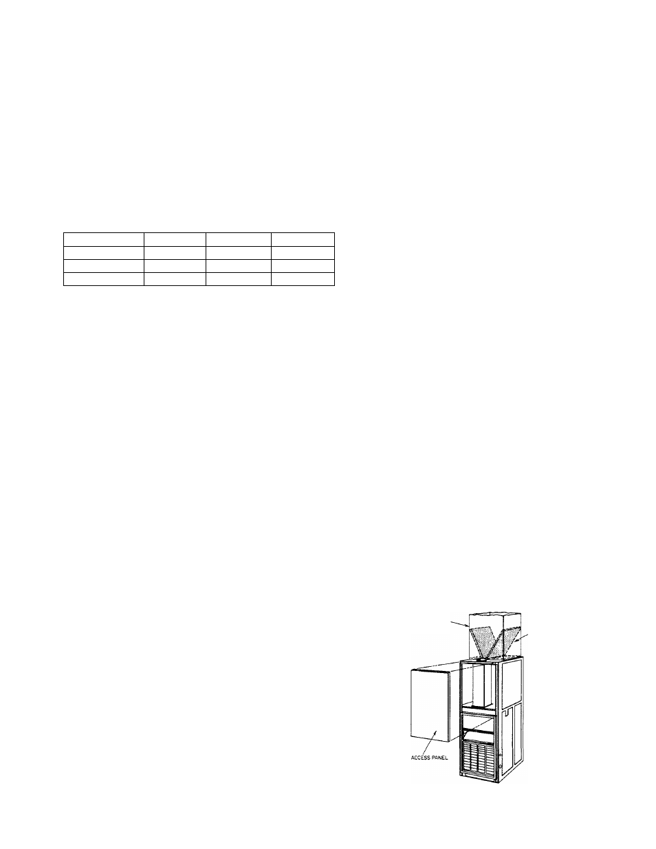
Vili. FILTER ARRANGEMENT
The two factory-supplied filters are shipped in the blower
compartment. After the return-air duct has been connected
to
the
fiurnace, install the filters in a V-formation inside the
return air plenum. See Figure 12.
WARNING:
Never operate unit without a filter or v/ith filter
access door removed.
RETURN-AIR
PLENUM
INSTALLATION
POSITION
(DF FILTERS
Figure 12—Position of Filters