Table ll-dimensions (in inches), Figure 2—dimensional drawing, Table lil-ratings and performance – Bryant 396G User Manual
Page 2: Figure 3 — floor opening for concrete siab, Table iv —opening dimensions
Attention! The text in this document has been recognized automatically. To view the original document, you can use the "Original mode".
1Л
ir
ф
Г'
г/
пг
.Q..
KNOCKOUT
ДиХ GAS
INLET
TABLE ll-DIMENSIONS (in Inches)
A78595
Size
A
D
E
Vent
024050
14-3/16
12-9/16
12-11/16
4
000075
IT-1/2
15-7/8
16-
4
036075
. 17-1/2
15-7/8
16
4
000100 .
17-1/2-
15-7/8
16
5
. 048100
17-1/2
15-7/8
16
5
000125
21
19-3/8
19-1/2
5
048125
21
19-3/8
19-1/2
5
060150
24-1/2
22-13/16
23
6
Figure 2—Dimensional Drawing
TABLE lil-RATINGS AND PERFORMANCE*
Size
Input
Btuh
Bonnet
Capacity
Btuh
Temp
Rise
Range
Heating
Cooling
Motor
HP&
Type
Approx
Ship.
Weight
Ext Static
Pressure
Ft3/Min
Ext Static
Pressure
Ft3/Min
024050
50,000
40,000
45-75
0.50
620
0.5
800
1/3-SP
127
000075
75,000
60,000
70-100
0.12
700
—
—
1/10-SP
146
036075
45-75
0.50
925
0.5
1255
1/3-SP
155
000100
100,000
80,000
70-100
0.20
870
—
—
1/5-SP
161
048100
60-90
0.50
990
0.5
1630
1/2-PSC
168
000125
125,000
100,000
70-100
0.20
1090
—
—
1/5-SP
185
048125
60-90
0.50
1235
0.5
1620
1/2-PSC
186
060150
150,000
120,000
55-85
0.50
1850
0.5
2075
1/2-PSC
225
*The above ratings are certified for altitudes to 2000 ft. For elevations above 2000 ft, reduce ratings 4% for each 1000 ft above sea level.
HOLE IN
FLOOR
3
VI. ELECTRICAL CONNECTIONS
A. Line-Voltage Wiring
IMPORTANT: Before proceeding with the electrical connec
tions, make certain that voltage, frequency, and phase cor
respond to that specified on the unit rating plate. Also, check
to be sure that the service provided by the utility is sufficient
to handle the additional load imposed by this equipment. Re
fer to the unit rating plate for equipment electrical require
ments.
CAUTION:
Do not connect aluminum wire between discon
nect switch and furnace.
See Figure 8 for wiring diagram showing the proper field
high- and low-voltage wiring. Make all electrical connec
tions in accordance with the National Electrical Code and
any local codes or ordinances that might apply.
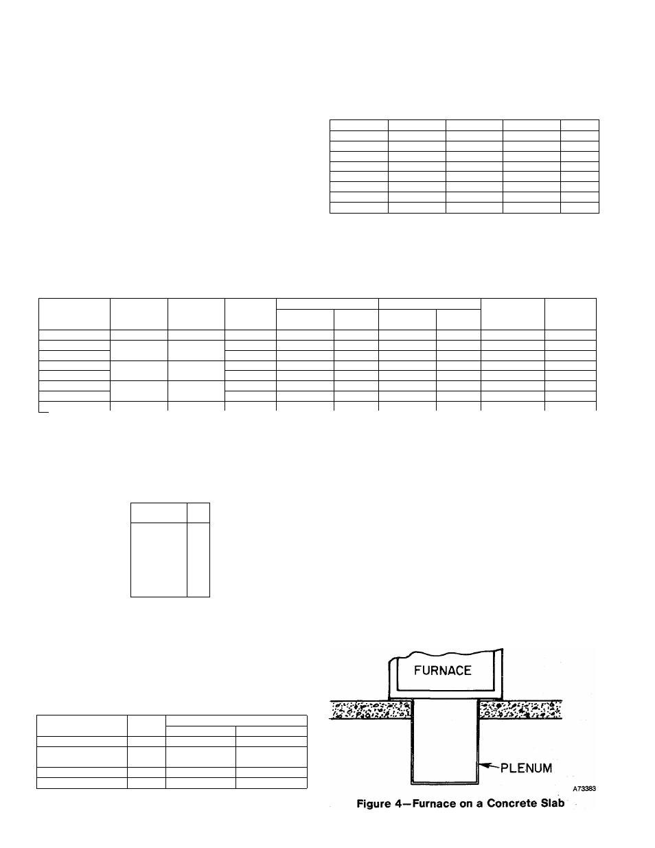
Figure 3 — Floor Opening for
Concrete Siab
TABLE IV —OPENING DIMENSIONS
Furnace
Size
A
В
Heat-Only
Heat/Cool*
024050
13-1/8
19-5/8
20-15/16
000075, 036075,
000100, & 048100
16-7/16
19-5/8
20-15/16
000125 & 048125
19-7/8
19-5/8
20-15/16
060150
23-7/16
19-5/8
20-15/16
These dimensions apply when a Model 518A Evaporator Coil casing
is to be installed.
-
2
-