Bryant 396G User Manual
Page 3
Attention! The text in this document has been recognized automatically. To view the original document, you can use the "Original mode".
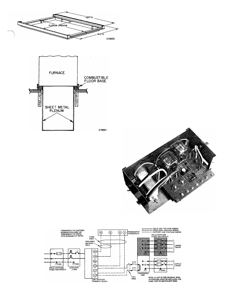
Figure 5—Combustible Floor Base
Figure 6—Furnace, Plenum, and
Base Installed on a Combustible Floor
Use a separate fused branch electrical circuit for this furnace.
A disconnecting means must be located within sight of, and
readily accessible to, the furnace. In some areas, the imit door
switch may qualify as the disconnecting means.
WARNING:
The furnace must be electrically grounded in
accordance with local codes, the National Electric Code, and
ANSI C1-1978. Do not use gas piping as an electrical ground.
If line-voltage wiring to the unit is encased in a nonmetallic
sheath, connect the incoming ground wire to the grounding
wire inside the furnace J-box. If metallic conduit is used, it
will serve as the ground.
B. Low-Voltage Wiring
Make field low-voltage connections at the low-voltage ter
minal strip. See Figure 8.
NOTE;
Use AWG No. 18 “color-coded” copper thermostat
wire for lengths up to 100 ft. Above 100 ft, use AWG No. 16
wire.
Set the thermostat heat anticipator at 0.5 for a furnace with a
BDP Model 646A Gas Valve; 0.6 for a furnace with an Essex
Model 242 Gas Valve; 0.2 when a Model 997A Vent Damper is
installed — no matter which of these gas valves is used. If
additional controls are connected in the thermostat circuit,
their amp draw must be added to this setting. A failure to
make this setting will result in improper operation of the
system.
For accurate reading, check the amp draw at the ther
mostat with an ammeter. A failure to make this setting
will result in improper operation of the system.
The room thermostat should be located where it will be in
the natural circulation path of room air. Avoid locations
where the thermostat would be exposed to cold-air infiltra
tion, drafts from windows, doors, or other openings leading
to the outside, or exposure to air currents from warm- or
cold-air registers; or to exposure where the natural circula
tion of the air is cut off—such as behind doors, above or
below mantels, shelves, etc.
The thermostat should not be exposed to heat from nearby
fireplaces, radios, televisions, lamps, or rays from the sun.
Nor should the thermostat be mounted on a wall containing
pipes or warm-air ducts, or a flue or vent that could affect its
operation and prevent it from properly controlling the room
temperature. Any hole in the plaster or panel through which
the wires pass from the thermostat should be adequately
sealed with suitable material to prevent drafts from affect
ing the thermostat.
A79077
Figure 7—Printed-Circuit Control Center
A78461
Figure 8—Heating and Cooling Application Wiring Diagram
-
3
-