050 thru 150 iid lpg – Bryant 396G User Manual
Page 4
Attention! The text in this document has been recognized automatically. To view the original document, you can use the "Original mode".
é.
Blower Control Center
Each furnace features a printed-circuit control center. This
will aid the installer and serviceman when installing and
servicing the unit. See Figure 7. A low-voltage terminal
board is marked for easy connection of field wiring.
VII. SEQUENCE OF OPERATION
NOTE:
The wiring diagram shown in Figure 9 covers heat
ing-only and Figures 10 and 11 cover heating/cooling.
A. Heating
Gas and electrical supplies must be turned on at the furnace.
NOTE:
When power is applied to heat relay coil 2A in the
control circuit, the normally closed contacts in the blower
circuit will open.
1: BDP 646 and Robeiishaw 7000 BKER Gas Valves
(IID Models)
When the thermostat “calls for hëàt,” thé control Circuit is
clpsèd between terminals R and W- JPowef from transformer
1À through fusible link liC and limit switches 7Hi/7H2
energizes the pilot valve portion of automatic gaS valve 5F
and pilot igniter 6F. The pilot valve opens, perinitting gas
flow to the pilot burner wheré it is ignited.
The pilot valve portion of automatic gas valve 5F is a
solenoid consisting of a “pick” and a “hold” coil. Both the
“pick” and the “hold” coils must be energized to open the
valve, but only the “hold” coil must be energized to
këep
it
open.
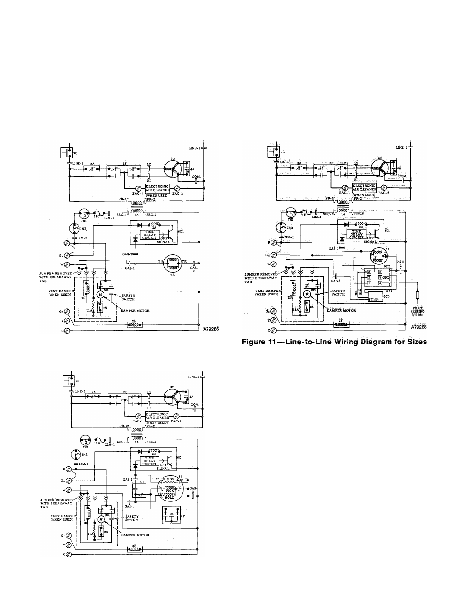
Figure 9—Line-to-Line Wiring Diagram for Sizes
050 thru 150 (match-lit pilot) Natural Gas & LPG
050 thru 150 IID LPG
LEGEND
ÍA^TranSfdFrñer 1l5/24
2A-Relay-Heat (SPST-N.G.)
2F-Relay-Cooi (DPDT)
3D-Blower Motor
4A-Run Capacitor
5E-GaS Valve....................................
5F-Gas, Valye (Two-Circuit)
6C1-Printed-Circuit Board
6C2-Pilot igniter and Flame Sensing
6C3-Lockout Timer Module
6F-Pilot Igniter
6H-Safety Pilot (Flame Sensing)
7H1-Limit Switch (SPST-N.C.)
7H2-Auxiliary Limit Switch (SPST-N.C.;
Manual Reset
9A-Summer/Winter Switch
9G-Blower Door Switch (SPST-N.C.)
IIA-Resistor
11C-Fusible Link
Figure 10—Line-to-Llne Wiring Diagram for Sizes
050 thru 150 IID Natural Gas