Table vi-speed selector, Common c hi 1 med-hi 2 med-low 3 low 4 – Bryant 396G User Manual
Page 6
Attention! The text in this document has been recognized automatically. To view the original document, you can use the "Original mode".
IX. STARTUP AND ADJUSTMENT
In addition to the following information, refer to "Procedures
for Gas-Fired Furnaces” packaged with the unit.
NOTE:
There is a switch located in the blower compartment
that breaks the electrical power supply when the blower ac
cess door is removed. Be sure blower access door is properly
installed.
CAUTION:
This furnace is equipped with a fusible link in
the vestibule area that will melt if an overheating condition
caused by an inadequate combustion air supply or improper
venting practices develops. Do not jumper this fuse. Correct
the condition and replace the fuse with an identical part.
A. Adjustment of Blower Speed
WARNING:
Disconnect the electrical power before chang
ing the speed tap.
To change motor speed taps, remove the motor tap lead (see
Table VI) and relocate it on the desired terminal on the
plug-in terminal block/speed selector located on the blower.
CAUTION:
When adjusting the blower speed, make certain
that the temperature rise across the heat exchanger does
not exceed that specified on the rating plate.
TABLE VI-SPEED SELECTOR
Speed
Tap No.
Common
C
Hi
1
Med-Hi
2
Med-Low
3
Low
4
B. Automatic Gas Control Valve
These units are equipped with an automatic gas control
valve. If not already checked when lighting the main
burner, check the proper operation of this valve by moving
the room thermostat pointer above and below room tempera
ture and observing that the main burners light on “call for
heat” and go off when the pointer is moved below room
termperature setting.
NOTE:
For ease of adjusting the pilot flame, disconnect one
power lead at main gas valve. For Model 646 Gas Valve, dis
connect terminal No. 1 and for match-lit models, disconnect
either lead. This will prevent main burner ignition and allow
time to adjust the pilot. Reconnect the power lead after
adjustment.
X. CARE AND MAINTENANCE
CAUTION:
Because of possible damage to the equipment or
personal injury, maintenance should be performed by
qualified persons only.
WARNING:
Never store anything on, or in contact with, the
furnace, such as:
1. Spray or aerosol cans, rags, brooms, dust mops, vacuum
cleaners, or other cleaning tools.
2. Soap powders, bleaches, waxes or other cleaning com
pounds, plastic or plastic containers, gasoline, kerosene,
cigarette lighter fluid, dry cleaning fluids, or other
volatile fluids.
3. Paint thinners and other painting compounds, paper
bags or other paper products.
For continuing high performance, and to minimize possible
equipment failure, it is essential that periodic maintenance
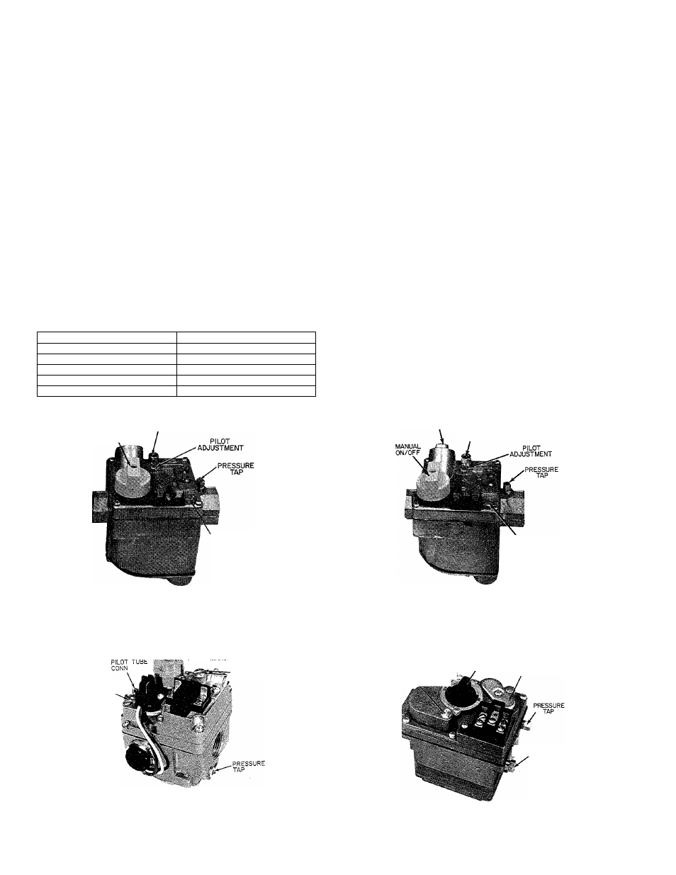
PILOT TUBE CONN
MANUAL ON/OFF
THERMOCOUPLE
CONN
REGULATOR
ADJUSTMENT
PILOT TUBE CONN
REGULATOR
ADJUSTMENT
A77243
Figure 13—Redundant Automatic Gas Control
Valve-BDP Model 646
Figure 15 — Redundant Automatic Gas Control
Valve — BDP Model 647
PILOT
ADJUSTMEN' ^
XL ON/OFF
__
regulator
ADJUSTMENT
THERMOCOUPLE
CONNECTION
(WHEN USED)
■ V
PILOT
ADJUSTM'^’“'^ ■“'*
MANUAL
ON/OFF
REGULATOR
ADJUSTMENT
f PILOT TUBE
CONN
A78487
Figure 14—Redundant Automatic Gas Control
Value —Robertshaw Model 7000 BKER
Figure 16 — Redundant Automatic Gas Control
Valve — Essex Model 242
-
6
-