Generator control panel, Remote start/stop panel, Before start-up – Generac Power Systems 9344-2 User Manual
Page 7: Remote start/stop panel before start-up, Operating instructions, Engine start/stop switch
Attention! The text in this document has been recognized automatically. To view the original document, you can use the "Original mode".
OPERATING INSTRUCTIONS
GENERATOR CONTROL PANEL
See Figure 3 to identify the following components;
■ HOURMETER___________ ___
Provides continuous indication of engine operating
time, in hours and tenths of hours. Use the hourme-
ter with the periodic maintenance tasks are completed
on a timely basis.
■ ENGINE START/STOP SWITCH_________
To crank and start the engine, hold switch at its
START position. Release the switch when the engine
starts. To stop an operating engine, press and hold
the switch in its STOP position until the engine shuts
off. The switch center position is the RUN position.
■ 10-AIVIP CIRCUIT BREAKER___________ _
Protects the DC control circuit against electrical over
load. If the fuse element has melted open due to over
loading, the engine cannot be cranked, engine preheat
and start functions cannot occur. The breaker is a
“push to reset” type.
Figure 3 — Generator Control Panel
PREHEAT SWITCH
GENERAC
NP75D
MOBILE GENERATOR
M DUAL AC CIRCUIT BREAKER___________
Rated at 35 AC amps, the circuit breaker (Figure 4) pro
tects the generator’s AC output circuit against overload
and provides a method of turning OFF the generator’s
120/240 volts AC output to vehicle circuits.
The diesel engine is equipped with glow plugs, one
for each cylinder. When you press the preheat switch
(Figure 3), the glow plugs heat the engine combustion
chamber for quicker starts in cold weather. To pre
heat the combustion chamber for quicker starts in
cold weather. Press the switch between 15 and 30
seconds. Continue holding in the preheat switch
while cranking the engine until it starts.
NOTE: Refer to THE GENERATOR AC CONNEC
TION SYSTEM on Page 4. Individual installations will
differ. If an overload occurs, the dual breakers will
open the hot stator leads (11 and 44). When the gen
erator has been connected for 120 volts only, one of
the dual circuit breakers will open stator AC output
lead No. 11 (hot lead).
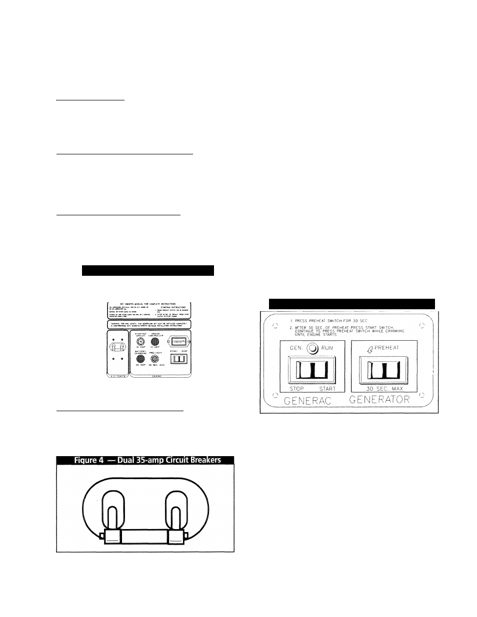
REMOTE START/STOP PANEL
A remote mounted Start/Stop Panel (model #9044) is
available, which allows you to start and stop the gen
erator engine conveniently from inside the vehicle
(Figure 5).
You can also order a remote panel (model #9061 )
that includes meters and gauges for monitoring low oil
pressure, high coolant temperature and low coolant
level, in addition to a start/stop switch. The panel
also includes an ammeter, a voltmeter and an
hourmeter.
Figure 5 — Remote Start/Stop & Gauge Panel
BEFORE START-UP
Check
Engine
Crankcase
Oil
Level:
Refer
to
SPECIFICATIONS and MAINTENANCE sections for pro
cedures and recommendations.
CAUTION! Any attempt to crank or start the engine
before properly servicing it with recommended oil
will result in an engine failure.
NOTE: Engine was factory serviced with a high quali
ty oil classified “For Service CD” or “For Service CC”
and having a viscosity rating of SAE 30. The installer
may have refilled the crankcase with an oil more suit
able for ambient temperature ranges in your area.
—
5
—