Maintenance, Periodic maintenance schedule, Overload protection for engine dc elec. system – Generac Power Systems 9344-2 User Manual
Page 12
Attention! The text in this document has been recognized automatically. To view the original document, you can use the "Original mode".
MAINTENANCE
PERIODIC MAINTENANCE SCHEDULE
* Performed by Authorized Service Facility
** Performed by Owner/Operator
A. After the first 25 Operating Hours*_______ _____
1. Change oil and oil filter.
2. Check engine coolant level.
3. Inspect cooling system,
4. Check engine operation.
5. Inspect drive belts.
6. Inspect exhaust system.
7. Inspect electrical system.
8. Inspect battery.
9. Check governed speed setting.
10. Check engine valve clearance.
11. Inspect air cleaner/flame arrestor.
12. Clean the generator.
B. Every 8 Hours of Operation**
1. Check coolant level in coolant recovery bottle.
2. Check fuel level.
3. Check engine oil level.
C. Once Each Week**______________________ ____
1. Inspect the generator set.
2. Inspect the generator battery.
D. Every 100 Hours or Once Each Month**________
(whichever comes first)
1. Inspect cooling system.
2. Inspect exhaust system.
E. Every 6 Months or Every 250 Operating Hours*
(whichever comes first)
1. Change engine oil and filter.
2. Check engine operation.
3. Inspect drive belts.
4. Inspect electrical system.
5. Inspect and check battery.
6. Check engine governor setting.
7. Clean or replace fuel filters.
8. Inspect air cleaner/flame arrestor.
9. Clean the generator.
10. Check cooling system and coolant level.
11. Inspect exhaust system.
12. Inspect fuel system.
F. Once Annually or Every 500 Operating Hours*
(whichever comes first)
1. Check engine valve clearance.
2. Check Engine compression and condition.
3. Check fuel injection timing.
4. Check-test fuel injection nozzles.
G. Once Every Two Years*__________
1. Drain, flush and refill cooling system.
OVERLOAD PROTECTION FOR
ENGINE DC ELECTRICAL SYSTEM
Engine cranking, start up and running are controlled
by a solid state engine controller circuit board.
Battery voltage is delivered to that circuit board via 10
amp circuit breaker and 14 amp in-line fuse. These
overcurrent protection devices will open if circuit is
overloaded.
CAUTION! If a circuit breaker opens or a
fuse element melts, you should find the
cause of the overload before resetting the
circuit breaker or replacing the fuse.
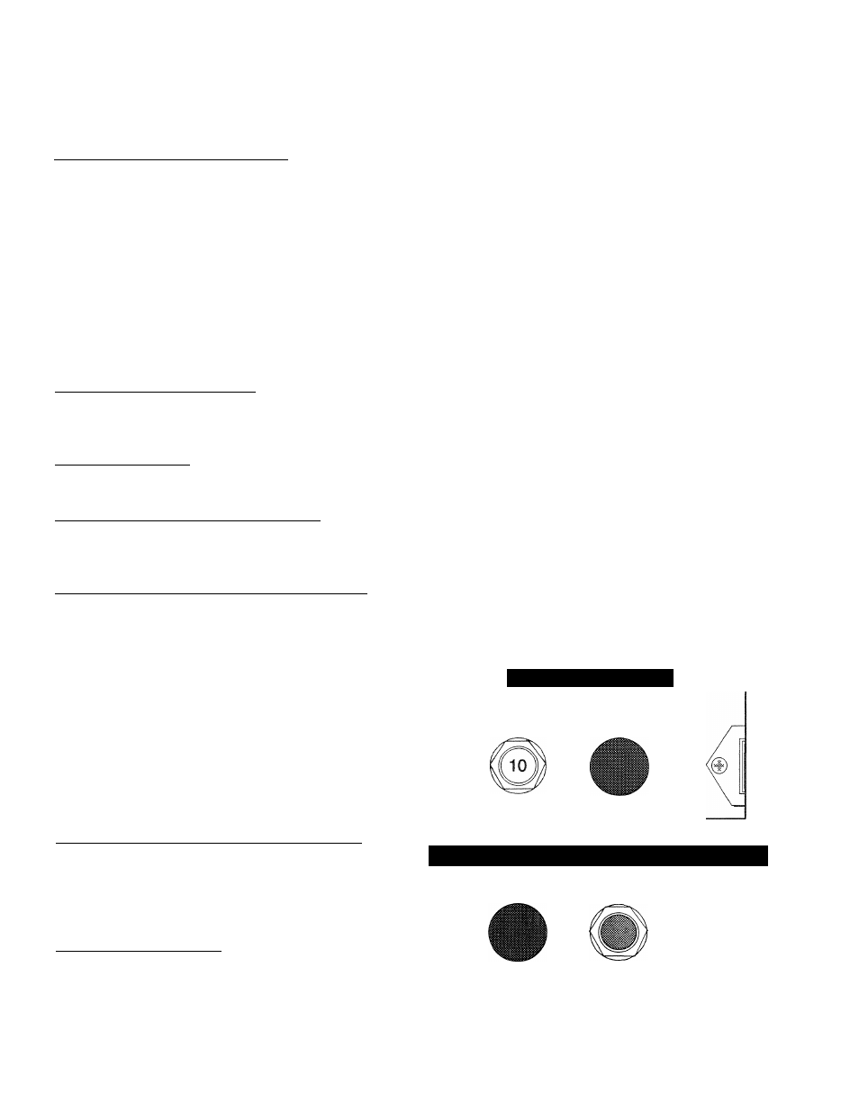
10 AMP CIRCUIT BREAKER
If the circuit breaker opens due to an overload, you
cannot crank or start the engine. The circuit breaker
is a “push-to-reset” type. For emergency shutdown,
pull the circuit breaker open. Also see “Generator
Control Panel” on Page 5.
14 AMP FUSE
If the fuse element melts open, you cannot crank or
start the engine. If you must replace the fuse, use
only identical 14 amp fuse (Figure 9).
30 AMP FUSE
The generator set battery is charged during operation
by a DC alternator, driven by the engine. This 30
amp fuse protects the charging circuit against over
load. Should you need to replace the fuse, use only
an identical 30 amp fuse (Figure 10).
Figure 9 — 14 Amp Fuse
S T A R T I N G E N G I N E
C I R G U I T C O N T R O L L E R
1 O A M P 1 4 A M P
Figure 10 —
30
Amp Fuse for Battery Charge Circuit
B A T T E R Y
C H A R G I N G P R E — H E A T
3 0 A M P 3 0 S E C . M A X
—
10
—