Front hanger, Adjustment nuts, Adjustor rod – Ariens 935000 User Manual
Page 38: Figure 32, Engine - figure 28, Fill fuel tank - figure 28, Dealer assembly & pre-service
Attention! The text in this document has been recognized automatically. To view the original document, you can use the "Original mode".
DEALER ASSEMBLY & PRE-SERVICE
CLEVIS PIN
FRONT HANGER
BELT
TIGHTENER
HAIR PINS BRACKET
WASHERS
figure
31
2
.
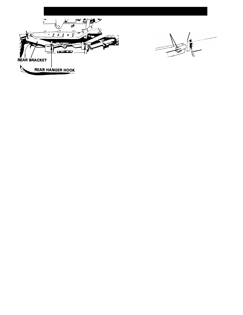
With the Attachment Lift Lever in the third lowest
cutting notch, measure the distance from surface
to mower blades at the front and rear of the pan.
The rear of the blades should be Vs inch higher
than the front and the blades should hang even
side to side.
3.
If adjustment is required, turn the hex nuts on the
rear hanger hooks to move the hooks up or down
to secure the proper adjustment. When the p?n is
leveled and hangs evenly, tighten the hex nuts.
See Figure 31.
4.
Adjust mower belt for proper center distance. See
Figures 14 and 32. Adjust nuts on the adjustor
rod connected to the center of the front axle to
move mower pan forward or backward. Adjust
1
to 1
’/2
inch clearance between belt as shown in
Figure 14 with mower pan in lowest and highest
positions.
CAUTION:
ADJUSTMENT
TOO
FAR
FORWARD
WILL
NOT
ALLOW
MOWER
BELT
TO
DECLUTCH!
CHECK
FOR
PROPER
MOWER
BELT
DECLUTCHING
IN
ALL
HEIGHT
POSITIONS.
IF
MOWER
BELT
DOES
NOT
DECLUTCH,
ADJUST
MOWER
PAN
BACKWARD
UN
TIL
PROPER
DECLUTCHING
OCCURS.
(PTO
SHEAVE
MUST NOT HAVE A TENDENCY TO DRIVE MOWER
BELT
A N D / O R
O V E R R I D E
B R A K E . )
A D V I S E
USER/OWNER
OF
THIS
PROPER
ADJUSTMENT
AND
CHECK PROCEDURE.
ADJUSTMENT NUTS
MOUNTING POST
ON FRONT AXLE
ADJUSTOR ROD-
BELT TIGHTENER BRACKET
HAIR PIN
FIGURE 32
WARNING:
THE
CHUTE
DEFLECTOR
MUST
BE
AT
TACHED TO THE 32" MOWER PAN ON THE YT8
YARD
TRACTOR
BEFORE
DELIVERY.
THE
TRACTOR
IS
SHIPPED
WITHOUT
THE
CHUTE
DEFLECTOR
IN
PLACE.
ATTACH
THE
CHUTE
DEFLECTOR
(035243)
TO THE MOWER PAN CHUTE WITH THE TWO CAR
RIAGE BOLTS (6201 7) INSERTED FROM THE INSIDE,
AND
SECURED
WITH
TWO
LOCKNUTS
(65040).
DEFLECTOR IS HELD DOWN BY THE CARRIAGE BOLT
( 6 2 0 4 2 )
AND
WING
NUT
(65064)
THROUGH
THE
FLANGE ON THE FRONT OF THE DEFLECTOR AND
PAN.
SEE
"MOWER
PAN
CUTTING
HEIGHT"
SEC
TION, PAGE 9, ALSO.
ENGINE - FIGURE 28
Use
high
quality
detergent
type
oil
with
service
designation SC, CC, SD, or SE. Oii weight specifica
tions
are
shown
in
"LUBRICATION"
section
of
this
manual.
FILL FUEL TANK - FIGURE 28
Fill fuel tank with "regular" grade gasoline. Do not use
premium gasoline.
NOTE: THIS PRODUCT IS EQUIPPED WITH AN INTER
NAL COMBUSTION TYPE ENGINE. DO NOT USE UNIT
ON
OR
NEAR
ANY
UNIMPROVED,
FOREST-COVERED
OR
BRUSH-COVERED
LAND
UNLESS
THE
EXHAUST
SYSTEM
IS
EQUIPPED
WITH
A
SPARK
ARRESTER
MEETING
APPLICABLE
LOCAL,
STATE
OR
FEDERAL
LAWS. A SPARK ARRESTER, IF IT IS USED, MUST BE
MAINTAINED
IN
EFFECTIVE
WORKING
ORDER
BY
THE
OPERATOR.
SEE
YOUR
ARIENS
DEALER
OR
ENGINE MANUFACTURER'S SERVICE CENTER.
- 3 8 -