Idler, Traction drive belt – Ariens 935000 User Manual
Page 10
Attention! The text in this document has been recognized automatically. To view the original document, you can use the "Original mode".
T8. Slide or drive, if necessary, “the jackshaft
downward
until
it
clears
the
top
PTO
Sheave. If the shaft must be driven use a %
or ®/g” diameter punch so as not to flatten
the top threads.
19.
With
the top PTO Sheave clear of the
jackshaft the Main Drive Belt can be un
wrapped.
20.
Slide rear of belt ahead and between upper
traction
and
lower
Attachment
Idler
assemblies. See Figure 11.
21.
Unwrap main belt from Engine Sheave and
remove from tractor.
B. Installation of New Belt
1.
Wrap new main belt around Engine Sheave.
2.
Feed other end rearward, above steering arm
and
through,
between
upper
Traction
and
lower Attachment Idler pivot assemblies.
3.
Push
Attachment
Idler
arm
upward
until
pivot
pin is
completely positioned through
the traction clutch idler arm pivot.
4.
Rotate Attachment Idler Arm so that hair pin
can be reinstalled
in
a forward direction.
Place washer over pivot pin and install hair
pin.
5.
Move Implement Clutch to "IN”.
6.
Feed PTO Rod between Main Drive Belt
lengths and install end through hole in At
tachment Idler Arm. See Figure 11.
7.
Install washer and cotter pin in PTO Rod.
8.
Connect Attachment Idler spring to anchor
on right front corner of transaxle. (Use vise
grips).
9.
Wrap main belt around lower (larger) groove
of top PTO Sheave. See Figure 1 2.
10.
Align top PTO Sheave bore above jackshaft
spindle bore and slide jackshaft upward and
through top PTO Sheave. Be sure spacer
washer is between upper spiindie bearing and
top PTO Sheave. See Figure 12.
11.
Insert key in PTO jackshaft and top PTO
Sheave assembly.
12.
Install internal tooth lockwasher on top’of
jackshaft and secure assembly with nut. Use
flats on bottom of jackshaft to hold'.
1 3. Reconnect Main Idler Spring to anchor hole
on left side of frame. Be sure Main Idler is on
backside of Main Drive Belt and spring is
above steering link. See Figure 11.
14. Grasp Traction Clutch Idler spring with vise
grips and connect hook to Traction Clutch
Idier Arm. See Figure 12.
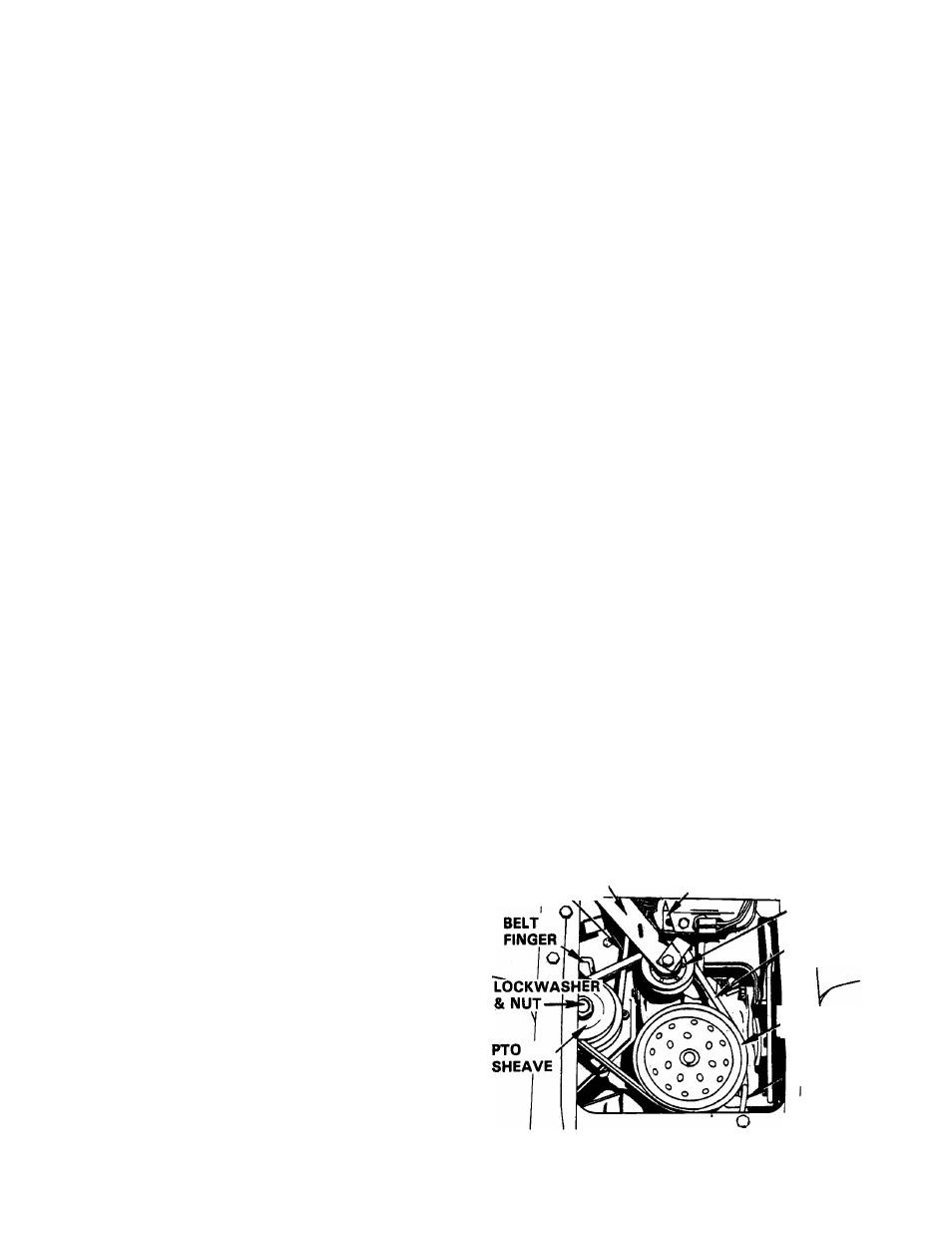
1 5. Depress traction clutch pedal and wrap Trac
tion Drive Belt around upper groove on PTO
Sheave
and
Transaxle
Sheave.
DO
NOT
PRY. See Figure 12.
16.
Release Clutch Pedal and align and tighten
traction belt fingers to Vie” to Ve” from belt.
17.
Move Implement Clutch Lever to "OUT”.
18.
Raise Attachment Lift Lever to highest posi
tion.
19.
Wrap
Mower
Belt
around
bottom
PTO
Sheave. DO NOT PRY.
20.
Re-align fingers around bottom PTO Sheave •
pulley Vie” to Vg” away from pulley and
tighten.
21.
Move Implement Clutch Lever to "IN” posi
tion.
22.
Attach Mower Brake Link to Stud under At
tachment Idler and secure with hair pin. See
Figure 8.
23.
Leave spark plug wire disconnected.
24.
Lower Attachment Lift Lever to lowest posi
tion.
25.
Move
Implement
Clutch
Lever
to
"OUT”.
Place Speed Selector Lever in "NEUTRAL".
26.
Crank engine with starter about six revolu
tions.
27.
Inspect Main Drive Belt and Main Idler for
alignment and clearance from sharp edges.
28.
Replace spark plug wire and test function.
TRACTION
MAIN CLUTCH
DRIVE 'CLE”
BELT
35026
I
CAM
TRACTION
ACTUATOR
IDLER
1
1
TRACTION
DRIVE BELT
TRANSAXLE
SHEAVE
■
1
BELT
FINGER
FIGURE 12
-10-