Troy-Bilt 15009 User Manual
Page 15
Attention! The text in this document has been recognized automatically. To view the original document, you can use the "Original mode".
8. Take two of the red plastic ties from the hard
ware bag. Locate them as shown in Photo 2-18.
Space them about two feet apart.
The serrated side of each plastic tie should be
on the inside of the loop when you wrap the tie
around the handlebar and Engine Throttle Lever
cable. Tighten each tie by pulling on the free
end. Snip off any excess with a scissor.
Photo 2-18: Secure Engine Throttle Cable to
Handlebars with two plastic ties.
STEP 8: ATTACHING THE
WHEEL GEAR LEVER TO THE
CONTROL PANEL (Econo-Horse
and Pony Models only)
The Wheel Gear cable is wrapped around the
transmission for shipping purposes. Unwrap the
cable and install it as follows:
1. Locate the last two #10-32 x 1/2" slotted head
screws, #10-32 nuts, and #10 lockwashers.
2. Position the Wheel Gear cable along the side
and up the left handlebar.
3. Position the Wheel Gear Lever beneath the
control panel. Insert the lever up through the slot
in the panel marked “WHEEL GEAR.”
4. Insert both of the screws through a “-h” mark
on the control panel decal. Align the holes in the
Wheel Gear Lever base with the screws and
place the base over the screws.
5. Double check to make sure that the screws go
through the holes in the lever’s base. Install a
lockwasher and nut on each of the screws. Use
a 3/8" wrench and a flat tip screwdriver.
%
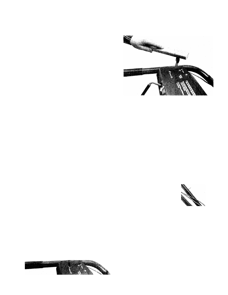
6. Place the Wheel Gear Lever knob on the end
of the Wheel Gear Lever. Use the piece of wood
to tap the knob until it seats on the lever.
Photo 2-20: Installing Wheel Gear Lever Knob.
(Econo-Horse and Pony Models only.)
\
7. Use the two remaining plastic ties in the hard
ware bag to secure the Wheel Gear cable to the
left-hand handlebar. Position the ties as shown
in Photo 2-21. Remember that the serrated side
of the tie should be on the inside when you loop
the tie around the handlebar and Wheel Gear
cable. After you’ve tightened the ties by pulling
on the loose ends, snip off any excess.
%
%
%
Photo 2-19: Installing the Wheel Gear Lever. (Econo-
Horse and Pony Models only.)
Photo 2-21: Secure Wheel Gear Cable to Handlebar.
(Econo-Horse and Pony Models.)
STEP 9: ADJUSTING THE AIR
PRESSURE IN THE TIRES
To be sure of a good seal between the tires
and wheels, we’ve inflated your tiller’s tires
above the recommended operating pressure.
Before using your tiller, be sure to evenly de
flate both tires until their pressure is 15 to 20 psi
(pounds per square inch). You can check the air
pressure with an automotive-type tire pressure
gauge.
Be sure that both tires have the same air pres
sure or the tiller will pull to one side when you
are using it.
13