Step 3: attaching the maneuvering clutch lever, Step 4: connecting the forward clutch rod – Troy-Bilt 15009 User Manual
Page 11
Attention! The text in this document has been recognized automatically. To view the original document, you can use the "Original mode".
3. Place the lower end of the handlebars on the
outside of the two mounting tabs on the top of
the transmission. Be sure the handlebar cross
brace (on the lower end of the handlebars) goes
under the curved height adjustment bracket.
4. Secure the lower ends of the handlebar to the
two mounting tabs with a 3/8"-16 x 1" bolt, a 3/8"
flat washer, and a 3/8"-16 nylon insert lock nut.
Use 9/16" wrenches. Both bolt heads should be
inserted from the inner side of the mounting tab.
5. On electric start models, move the curved
height
adjustment
bracket
back in
place.
Reinstall the bolt and lockwasher you previously
removed. Tighten both bolts very securely.
6. Move the handlebar up (or downward) to align
the hole in the handlebar cross brace with one of
Photo 2-6: Attaching the handlebars.
the four slots in the curved height adjustment
bracket. See Photo 2-7. Place the keyed washer
on the Height Adjustment Handle. Screw the
handle into the hole in the handlebar cross
brace. Make sure that both raised keys on the
bottom of the keyed washer fit into one of the
four slots on the bracket. Tighten the Handlebar
Height Adjustment Handle securely. Also tighten
the hardware securing the ends of the handlebar
to the two mounting tabs.
STEP 3: ATTACHING THE
MANEUVERING CLUTCH LEVER
1. Slide the Maneuvering Clutch Lever down
through the hole in the left-hand side of the han
dlebar control panel. Make sure that the
Maneuvering Clutch Lever passes above the
cross brace on the lower end of the handlebar.
2. Turn the Maneuvering Clutch Lever so the
small bend on the lower side points inward.
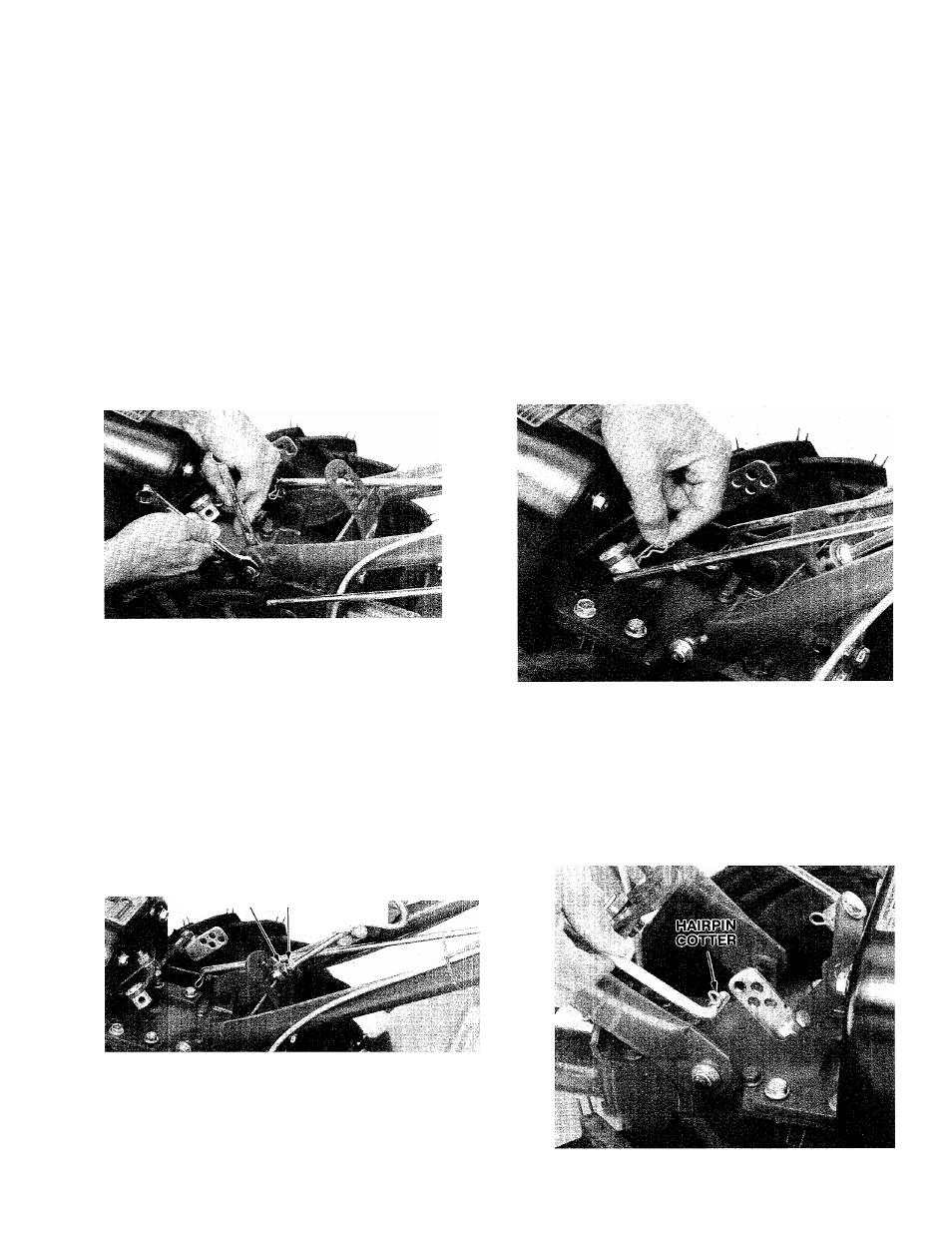
3.
Insert the lower end of the Maneuvering
Clutch Lever into the hole in the pivot as shown
in Photo 2-8. Secure the Maneuvering Clutch
Lever in place by inserting a hairpin cotter down
through the hole in the end of the Maneuvering
Clutch Lever.
Photo 2-8: Installing Maneuvering Clutch Lever.
STEP 4: CONNECTING THE
FORWARD CLUTCH ROD
1.
Turn the Forward Clutch Rod so the small
bend at the lower end points inward.
2. Insert a hairpin cotter down into the inner hole
in the small bend of the Forward Clutch Rod.
KEYED
WASHER
lockwasher
Photo 2-7: Installing the Handlebar Height Ad
justment Handle.
7. With the handlebars installed, you can now
easily move the tiller off its shipping platform.
Note: Out in the garden you may need to
readjust handlebar height again for comfort.
See Handlebar Height Adjustment, page 21.
Photo 2-9: Connecting the Forward Clutch Rod.