Electrical information – SINGER 301 User Manual
Page 3
Attention! The text in this document has been recognized automatically. To view the original document, you can use the "Original mode".
• SELF-SETTING NEEDLE makes it impos
sible to insert needle incorrectly in clamp.
• FEED THROW-OUT DEVICE permits darn
ing and embroidering without attachments.
• RECESSED BOBBIN WINDER—equipped
with automatic stop — it can’t break or tangle
your thread.
• HINGED BED EXTENSION permits quick
and easy removal of bobbin.
• HINGED FACE PLATE—Simplifies clean
ing and oiling.
• DIAL TENSION takes the guess work out
of upper tension setting.
• FLEXIBLE SPOOL PINS — bend but do
not break—thread unreels smoothly and easily.
•COMPLETELY
ENCLOSED
motor
and
principal working parts insure maximum
safety.
E L E C T R I C A L I N F O R M A T I O N
The SINGER"^ electric motor
in your sewing machine is furnished for oper
ation on an alternating current of 110-120
volts, 25 to 75 cycles, or on 110-120 volts
direct current. Special motors can be provided
through your SINGER SEWING CENTER
for direct or alternating current for any volt
age between 20 and 250, and for 32 volts
direct current.
Before Inserting Electric Plug—
be sure that the voltage and the number of
cycles stamped on the motor nameplate are
within the range marked on your electric
meter installed by your power company.
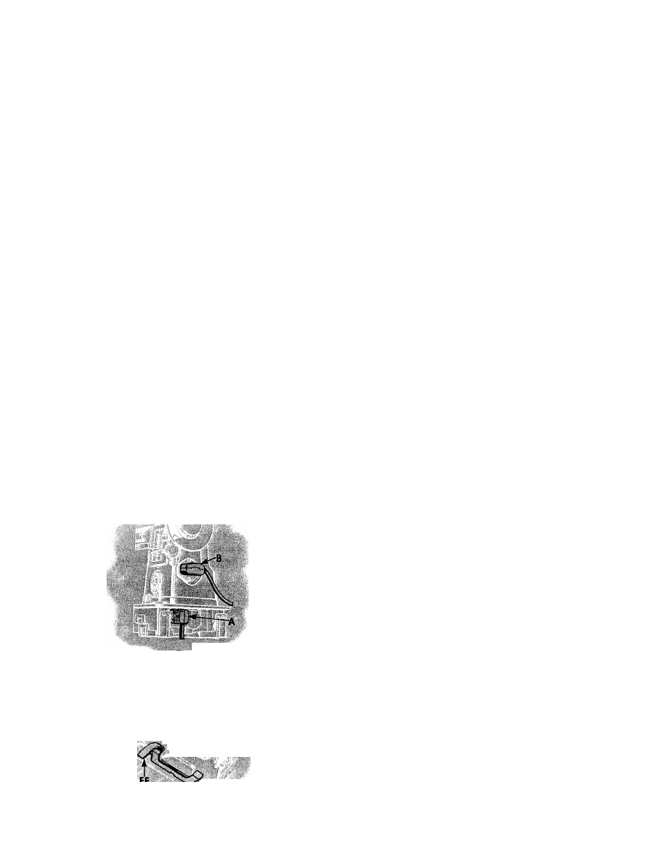
Fig, 1, Electrical Connections
for Machine
E L E C T R I C A L C O N N E C T I O N S F O R M A C H I N E
Push 2-pin terminal plug A, Fig. 1 on 2-pin terminal block at
right end of bed.
Push 3-pin terminal plug B, Fig. 1 on 3-pin terminal block at
right of machine and connect plug at other end of cord to
electrical outlet.
Speed Controller
The speed of machine is regulated by amount of pressure on
the pedal of the foot controller or the knee lever.
T O U S E T H E 3 0 1
a s
a
p o r t a b l e
m a c h i n e
Fig. 2. Showing Latch for Releasing
Machine fron\ Cabinet
To remove the machine from the cabinet, disconnect the 3-pin
terminal plug B, Fig. 1, lift handle C, Fig. 3, raise bed ex
tension at left, depress latch FF, Fig. 2, and lift out machine.
Disconnect 2-pin terminal plug A, Fig. 1 and set machine
aside. Then remove controller from its holder in cabinet by
pulling it downward. With machine set on a suitable surface
near an electrical outlet, reconnect 2-pin and 3-pin terminals
and place foot controller on floor.