If correct stitching is not obtained – SINGER 301 User Manual
Page 12
Attention! The text in this document has been recognized automatically. To view the original document, you can use the "Original mode".
23
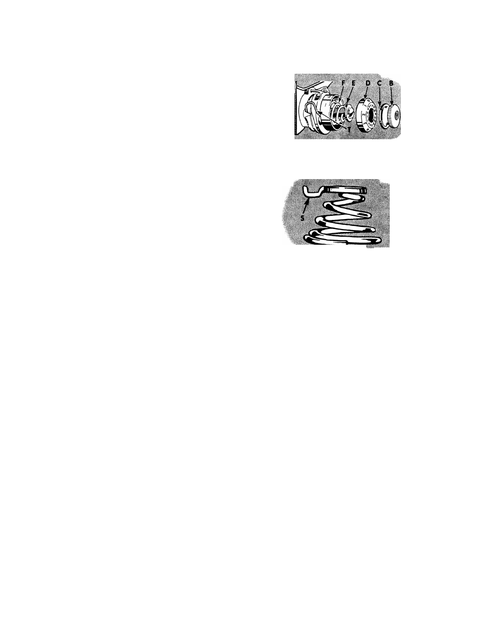
Place tension disc assembly on stud O so that extension K
enters hole in machine and tail (inside the coil) of thread take-
up spring enters one of grooves in the stud. Next replace indica
tor G, open side out, on stud with plus and minus signs at top
and hold parts, thus assembled, against shoulder of stud. Then
insert tension spring F in indicator with first (half) coil of
spring straddling lower half of stud. Place stop washer E on
stud with extension S above stud. If spring and stop washer are
in correct position, extension S will clear first (half) of tension
spring, as shown in Fig. 28.
Next, place dial D on stud with No. 2 opposite stop washer ex
tension S, then push dial to compress tension spring and at the
same time screw thumb nut B on stud, inserting pin C on nut
in one of the holes in dial D. Then lower presser bar and turn
thumb nut B to left until on dial D stops at centerline on
indicator G. Thread the tension and pull thread through tension
discs to test amount of tension on thread at the
position.
At this point there should be a slight pull on the thread to in
dicate that there is a minimum tension which gradually in
creases with the turning of thumb nut B to the right, provid
ing a full range of tensions with one revolution of the thumb nut.
Fig. 27. Reassembling
Needle Thread Tension
Fig. 28. Stop Washer and Tension Spring
24
If the pull is too strong for a minimum ten
sion, press in dial D to disengage pin C on
nut from dial, and reset pin in one of holes at
left of previous setting. This resetting will pro
duce less tension at ^^O.” Repeat this process
until minimum desired tension is obtained.
If there is no tension at
press in dial D
and reset pin C on nut in one of holes at right
of previous setting, repeating this process until
a slight minimum tension is obtained.
The tension on thread take-up spring T and
stroke of this spring should be just sufficient
to take up slack of needle thread until eye of
needle reaches goods in its descent.
To adjust tension on thread take-up spring T,
remove tension disc assembly, disengage end
of spring from groove in tension stud, revolve
spring and place its end in the groove which
produces correct tension.
For average weights of materials, the stroke of
thread take-up spring T should release the
thread after the needle point has entered the
fabric, i.e., halfway between the point and eye
of the needle. To regulate stroke, loosen screw
U, Fig. 23 and turn the thread take-up spring
regulator V, Fig. 23 until correct stroke is ob
tained, then tighten screw U.
I F C O R R E C T S T I T C H I N G I S N O T O B T A I N E D
If bobbin thread tension has been disturbed,
or a correct stitch cannot be obtained without
a very heavy or very light needle thread ten
sion, the following procedure is recommended.
Using Size 50 Mercerized thread in needle and
on bobbin, adjust needle thread tension as in-
' striicted on page 23. Then turn tension thumb
nut until No. 4 on dial is opposite centerline
on indicator and, with two thicknesses of thin
material in machine, adjust bobbin thread ten
sion, as instructed on page 21, until stitch is
correctly locked in material, as shown in
Fig. 20.
A wide range of materials and threads can now
be accommodated without further adjustment
of bobbin thread tension.