To regulate bobbin thread tension, To remove and disassemble ne 4.e thread tension, To reassemble and replace needle thread tension – SINGER 301 User Manual
Page 11
Attention! The text in this document has been recognized automatically. To view the original document, you can use the "Original mode".
21
T O R E G U L A T E N E E D L E T H R E A D T E N S I O N
The tension on needle thread can be tested
only when presser foot is down.
The numerals “0 to 9”
on dial D, Fig. 23 in
dicate different degrees
;y| of tension that can be
3o b t a i n e d. The num
bers do not denote size
of thread or ounces of
tension.
J
'T
•
When tension has been
NeedLe I firead 1 ension
,
correctly set as de
scribed on pages 23 and 24, note number at
indicator line G so that this setting may be
regained should the tension be altered for
special work.
To increase tension, turn thumb nut B
gradually to right (clockwise) until required
tension is obtained. Each higher number de
notes increased tension.
To decrease tension, turn thumb nut B
gradually to left (counter-clockwise) until re
quired tension is obtained. Each lower num
ber denotes less tension.
The tension indicator G is marked with the
signs -f- and —, which indicate the direction
in which to turn the thumb nut B for more
or less tension.
T O R E G U L A T E B O B B I N T H R E A D T E N S I O N
The tension on bobbin thread is regulated by
screw AA, Fig. 24 which is nearest center of
tension spring on outside of bobbin case. To
increase tension, turn screw AA over to right.
To decrease tension, turn
this screw over to left.
^
When tension on bobbin
thread has been once prop
erly adjusted, it is seldom
necessary to change it, as a
correct stitch can usually be
obtained by varying tension
on needle thread.
Fig. 24. Bobbin Thread Tension
22
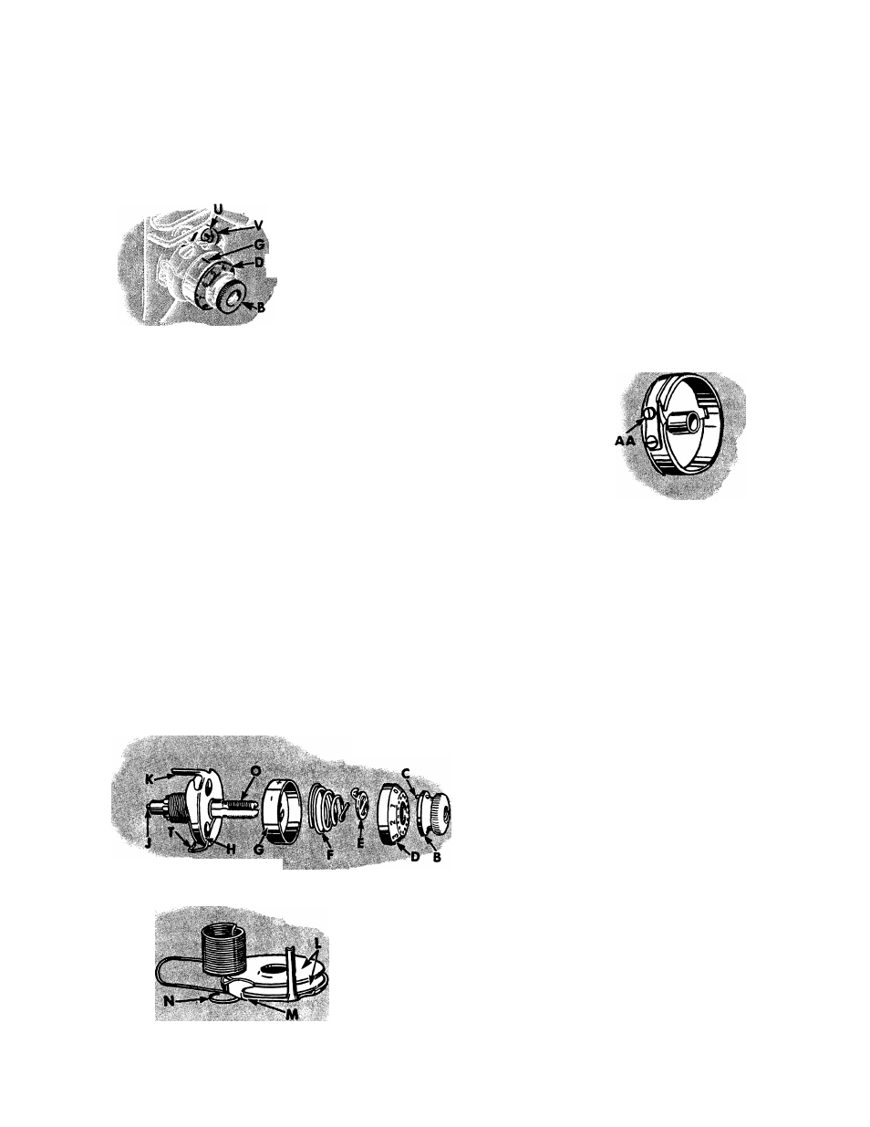
Fig. 25. Needle Thread Tension Disassembled
T O R E M O V E A N D D I S A S S E M B L E N E 4 . E T H R E A D T E N S I O N
Turn thumb nut B to left (counter-clockwise) until ‘‘O” on
numbered dial stops at cente** bne on indicator G.
To separate pin C in thumb nut B from dial
D, press in dial, unscrew thumb nut and re
move it. Then remove dial, stop washer E,
tension spring F, indicator G and tension
assembly H.
NOTE: It is not necessary to remove stud O
from machine to disassemble the thread ten
sion. It is shown removed in Fig. 25, only
to illustrate the complete assembly.
Fig. 26. Tension Disc Assembly
T O R E A S S E M B L E A N D R E P L A C E N E E D L E T H R E A D T E N S I O N
Make sure that tension releasing pin J is in place in stud O.
Place two tension discs L with their convex faces together on
tension thread guide M, then pass eyelet N of thread take-up
spring under thread guide, having coils of spring above ten
sion discs, as shown in Fig. 26.