Attaching the spur gears to their shafts fig.23, Adjusting the low-speed cam position – SINGER 1371A2 User Manual
Page 30
Attention! The text in this document has been recognized automatically. To view the original document, you can use the "Original mode".
5) The machine head installed a couple of gears (symbol N)for 137lAl; The oter three couples
of gears (symbol G, J, L) are as accessories.
The machine head installed a couple of gears (symbol L)for 1371A2; The oter three couples
of gears (symbol J^ N) are as accessories.
The machine head installed a couple of gears (symbol H)for 1371A3; The oter four couples
of gears (symbol G, J, N) are as accessories.
Symbol
No. of stitches No. of stitches
Symbol
No. of stitches No. of stitches
A
54
345
I
93
200
B
62
300
®
100
190
C
66
285
K
105
180
D
70
268
©
110
170
E
74
252
M
115
160
F
79
238
®
123
152
©
83
225
0
130
145
H
88
212
number of stitches provided by the combination of spur gears.
The circled alphabetical symbols in the above table show that the gears are included in
the standard accessories. All other gears are optional attachments.
* Attaching the spur gears to their shafts
Fig
.23
1) Push gear (D into the shaft so that it is securely fixed by the pin on gear bushing (D
located nearer to an operator.
2) For installing gear
(D
on the pin of rear gear bushing
® ,
push gear ® into the shaft
while turning it in the arrow direction.
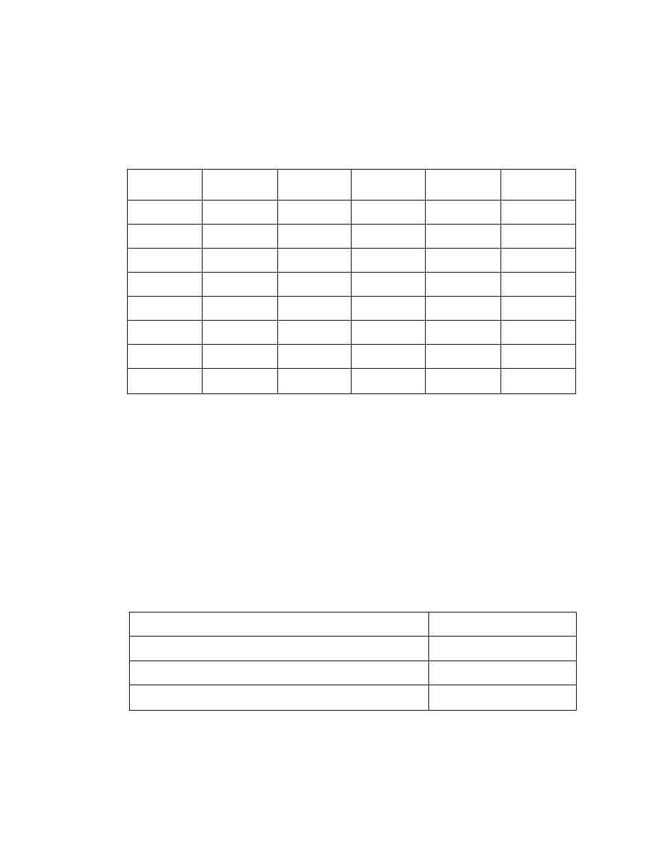
* Adjusting the low-speed cam position
Loosen setscrews
(D,
and adjust the position of low-speed cam
(D
to set clearance
®
as
shown below:
Number of stitches
Clearance ®
93 stitches or less
10—12 mm
115 stitches or less
5 mm
123 stitches
0~2mm
27