Turn ignition key "off" and remove key, Lawn rider, To remove mower (see fig. 21) – Sears 917.257462 User Manual
Page 18: To install mower (see fig. 21), Mower upstop adjustment (see fig. 22), Service and adjustments
Attention! The text in this document has been recognized automatically. To view the original document, you can use the "Original mode".
SERVICE AND ADJUSTMENTS
A
CAUTION: BEFORE PERFORMING ANY SERVICE OR ADJUSTMENTS:
Depress clutch/brake pedal fully and set parking brake.
Place gearshift lever in "NEUTFIAL" position.
Piace attachment clutch in "DISENGiAGED“ position.
Turn ignition key "OFF" and remove key.
Make sure the blades and ail moving parts have completely stopped.
Disconnect spark plug wire from spark plug and place wire where it cannot come in contact with
plug.
LAWN RIDER
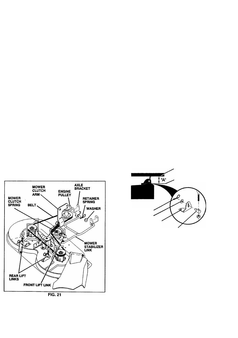
TO REMOVE MOWER (See Fig. 21)
Mower will be easier to remove from the right side of unit.
• Park tractor on a level surface and engage parking
brake.
Remove key from ignition.
Be sure that mower clutch lever is in "DISENGAGED"
position.
Lower mower deck to lowest cutting position.
Remove retainer spring and washer that holds mower
clutch spring to the mower clutch arm.
Disconnect mower clutch spring from mower clutch
arm.
Remove retainer springs and washers from mower
stabilizer link.
Remove retainer springs and washers from rear lift
links.
Remove retainer spring and washer from front lift link.
Withdraw front lifts links, rear lift links and mower
stabilizer link from axle brackets.
Remove belt from engine pulley.
Raise mower lift handle to transport position.
Turn front tires to left.
Slide mower deck out on right side of tractor.
TO INSTALL MOWER (See Fig. 21)
•
Reverse removal instructions.
MOWER UPSTOP ADJUSTMENT (See Fig. 22)
•
Raise mower lift lever to highest (transport) position.
•
Measure distance from top of mower deck to lower
flange of chassis (dim. "A").
•
Dim. "A" should be 3-3/8 to 3-1/2 inches.
•
To adjust dim. "A", if required, lower mower to lowest
position. Remove washer and retainer .spring in trun
nion, then withdraw trunnion pin from bracket. Loosen
iower trunnion locknut and rotate trunnion counter-
ciockwise on lift link to increase dim. "A" or clockwise
on lift link to decrease dim. A".
•
Tighten iower trunnion locknut.
NOTE:
Each full turn of trunnion will change dim. "A" by
1/16 inch. Re-insert trunnion into bracket with pin pointing
to LH. side of unit. Re-install washer and retainer spring.
•
Raise lift lever to highest position and recheck dim. "A".
Repeat adjustment if necessary.
LOWER FLANGE
OF CHASSIS
TOP OF MOWER DECK
RETAINER SPRING
WASHER
BRACKET
FRONT UFT TRUNNION
FIG. 22
18