Installing sliding guard, Iristaliing sliding guard, 1/2 in. hex nut – Sears 113.206930 User Manual
Page 9
Attention! The text in this document has been recognized automatically. To view the original document, you can use the "Original mode".
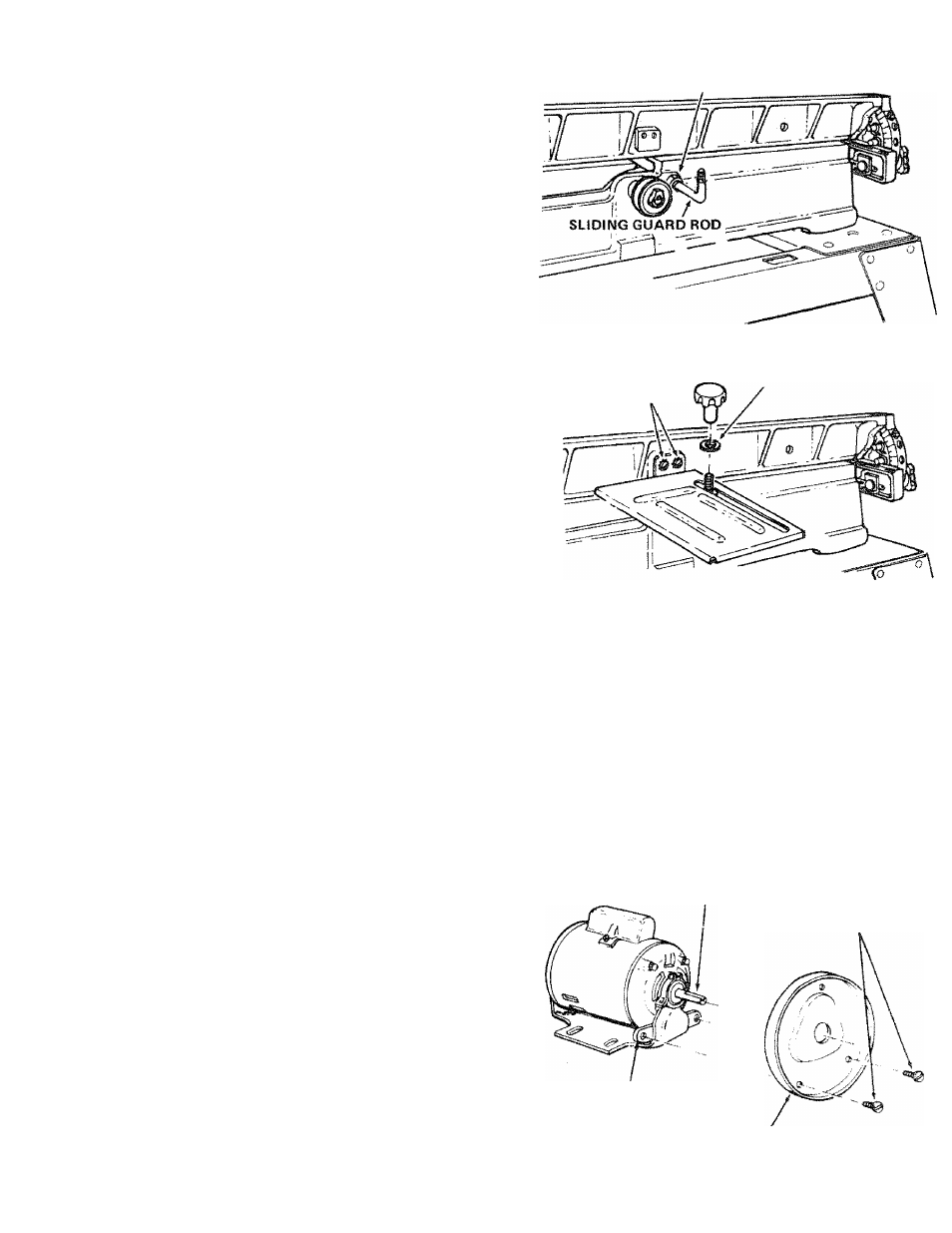
INSTALLING SLIDING GUARD
PARTS NEEDED
1 Sliding Guard
1 Sliding Guard Knob
1 Sliding Guard Rod
2 Sliding Guard Washers (one side of washer is concave)
1 Hex. Nut
M 2
in, -13
1 Spiit tockwasher 1/2 in.
2 Ext. tooth lockwashers
2 10-32x1/4 Pan Hd. Screws
1. Screw nut all the way onto long end of rod . . . place
1/2 in. lockwasher next to nut.
2. Screw rod all the way into Jointer with short end up . ..
tighten nut.
1/2 IN. HEX NUT
SLIDING GUARD KNOB
10-32x1/4 SCREWS
WASHER
{CONCAVE SIDE UP)
3. Attach sliding guard to fence with two machine screws EXT. TOOTH
and lockwashers.
LOCKWASHER^
4. Place one Sliding Guard Washer, concave side DOWN on
support rod.
5. Drop sliding guard onto rod ... place other washer, con
cave side UP on rod . . . screw on Sliding Guard Knob.
MOUNTING RECOMMENDED CRAFTSMAN
MOTOR AND BELT GUARDS
See page 5 for recommended motors.
PARTS NEEDED
4 carriage bolts, 5/16-18 x 3/4 in., flat washers, lock
washers and nuts.
1 Jointer Planer Belt Guard
1 Motor Pulley Belt Guard
1 Belt Guard Support
1 Belt Guard Support Bracket
3 Belt Guard Clips
1 Motor Pulley, 2-1/2 in. dia,
1 V-Belt
_
2 Pan Head Screws 10 - 32 x 1/2 in.
2 Hex. Hd. Screws 1/4 - 20 x 1/2 in.
2 Hex. Nuts 1/4-20
TOOLS NEEDED
Medium Screwdriver
5/32 in. Setscrew Wrench (furnished with Jointer)
1/2 and 7/16 in. Wrenches
1. Place motor on your workbench with 5/8 in. dia. shaft
(with key way) facing you.
2. Attach guard support to bracket with two screws.
NOTE: The holes in the bracket are not threaded, but
the screws are "thread cutting screws" and will cut a
thread as they are tightened.
S/8 IN. DIA. SHAFT
BELT GUARD
SUPPORT
BRACKET
PAN HD. SCREWS
BELT
GUARD
SUPPORT