Unpacking and check ii, Tools needed, One carton but does not include steel legs, or – Sears 113.206930 User Manual
Page 6
Attention! The text in this document has been recognized automatically. To view the original document, you can use the "Original mode".
unpacking and check ii
TOOLS NEEDED
1/2" Wrench
7/16" Wrench
3/4" Wrench
3/8"Wrench
iVledium Sctewdriver
Model 113.20680 Jointer/Planer is shipped complete in
one carton but DOES NOT INCLUDE Steel Legs, or
^ ^ ^ '■ ■ ' '
Model 113.206930 Jointer/Planer is shipped complete in
one carton but INCLUDES Steel Legs, and Motor.
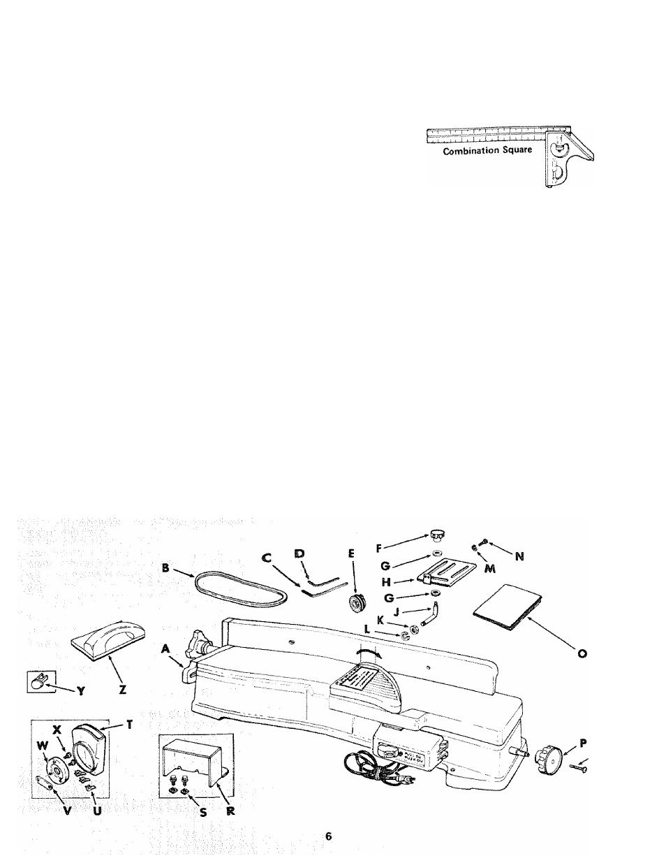
Separate all parts from packing materials and check each
one with the illustration and the list of Loose Parts to make
certain all items are accounted for, before discardirsig any
packing material.
^
-
If any parts are missing, do not attempt to assemble the
jointer/planer, plug in the power cord or turner the switch
on until the missing parts are obtained and are installed
correctly.
Remove the protective oil that is applied to all unpainted
metal surfaces. Use any ordinary household type grease and
spot remover.
:
CAUTION: Never use gasoline, naptha or stnnilar highly
volatile solvents.
Apply a coat of automobile wax to the table.
Wipe all parts thoroughly with a clean, dry cloth .
WARNING: FOR YOUR OWN SAFETY^, WEVER
CONNECT PLUG TO POWER SOURCE OUTLET UNTIL
ALL ASSEMBLY STEPS ARE COMPLETE. AND YOU
HAVE READ AND UNDERSTAND THE SAFETY AND
diPERATIONALINSTRUCTiONS.
TABLE OF LOOSE PARTS
Item
No,
A
B
C
D
E
F
G
H
J
K
L
M
N
0
P
Q
R
S
T
u
V
w
X
Y
z
Description
Qty.
Jo inter-Planer ..................................................... i
V-Beit, 1/2 x52" ................................................... 1
5/32 Setscrew Wrench ........................................ 1
1/8 Setscrew Wrench ................................ .. • • •
1
Motor Pulley, 2-1/2" Dia..................................... 1
Sliding Guard Knob ................................................ 1
Concave Washer............................................... 2
Sliding Guard .......................................................... 1
Sliding Guard Rod................................................. 1
Nut, 1/2-13 .............................................................. 1
Lockwasher, 1/2 ..... ............................................... 1
Lockwasher, No. 10
2
Screw, Pan Hd., 10 - 32 x 1/4 ................................. 2
Owners Manual ...................................................... 1
Depth of Cut Handwheel ........................................ 1
Screw, Sems, 1 /4 - 20 x 1 -1 /4 ............................. 1
, 1
.
1
. 3
.
1
. 1
. 1
. 2
Jointer-Planer Belt Guard
Attaching Hardware (2 Nuts, 2 Bolts)
Motor Pulley Belt Guard .......................
Belt Guard Clips ....................................
Belt Guard Support Bracket .................
Belt Guard Support ...............................
2 self tapping screws
Switch Key .............................................
Hold Down/Push Block .................
o