A caution – Carrier 48N User Manual
Page 5
Attention! The text in this document has been recognized automatically. To view the original document, you can use the "Original mode".
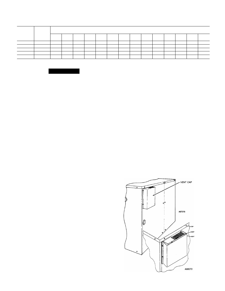
Table 1—Maximum Gas Flow Capacity of Pipe in Cubic Feet of Gas Per Hour for Gas
Pressures of 0.5 PSIG or Less and a Pressure Drop of 0.5 inch Water Coiumn
(Based on a 0.60 Specific Gravity Gas)
Nominal
Iron Pipe,
Size,
Inches
Internal
Diameter,
Inches
Length of Pipe, Feet*
10
20
30
40
50
60
70
80
90
100
125
150
175
200
1/2
.622
175
120
97
82
73
66
61
57
53
50
44
40
—
—
3/4
.824
360
250
200
170
151
138
125
118
110
103
93
84
77
72
1
1.049
680
455
375
320
285
260
240
220
205
195
175
160
145
135
1-1/4
1.380
1,400
950
770
600
580
530
490
460
430
400
360
325
300
280
1-1/2
1.610
2,100
1,460
1,180
990
900
810
750
690
650
620
550
500
460
430
Ref: Table 0^4, NFPA 54—1984
*This length includes an ordinary number of fittings.
A CAUTION
The venting system is designed to ensure proper vent
ing. The vent cap assembly must be installed as indi
cated
in
this
section
of
the
unit
Installation
Instructions.
NOTE:
Screw holes in the flue assembly and the unit flue
panel are
not
symmetrically located; thereby, ensuring
proper orientation when installing these components.
Refer to Fig. 6 and install the vent cap as follows:
1. Place vent cap assembly over flue panel, orient screw
holes in vent cap with holes in flue panel, and secure
vent cap in place by inserting the single screw on the
right side of vent cap.
2. Place the vent cap guard over the vent cap, orient holes
in vent cap guard with holes in vent cap and flue panel.
Secure the entire assembly with the remaining two
screws on the left side of vent cap and vent cap guard
assembly.
Step 4—Gas Piping
The gas supply pipe enters the unit through the access hole
provided. The gas connection to the unit is made to the
1/2-in. FPT gas inlet on the manual shutoff or gas valve.
Install a separate gas supply line that runs directly from
the meter to the heating section. Refer to Table 1 and the
National Fuel Gas Code for gas pipe sizing.
Do not use cast-
iron pipe.
Check the local utihty for recommendations con
cerning existing lines. Choose a supply pipe that is large
enough to keep the pressure loss as low as practical.
Never
use pipe smaller than the 1/2-in. FPT gas inlet on the unit
gas valve.
When instaUing the gas supply hne, observe local codes per
taining to gas pipe installations. Refer to the National Fuel
Gas Code ANSI Z223.1-1984 (In Canada, CAN/CGA
B 149.1, (2)-M86) or NFPA 54-1984 in the absence of local
buUding codes. Adhere to the following pertinent recom
mendations:
1. Avoid low spots in long runs of pipe. Grade aU pipe
1/4-in. in every 15-ft to prevent traps. Grade all hori
zontal runs downward to risers. Use risers to connect
to heating section and to meter.
2. Protect all segments of piping system against physical
and thermal damage. Support all piping with appropri
ate straps, hangers, etc. Use a minimum of one hanger
every 6-ft. For pipe sizes larger than 1/2-in., follow rec
ommendations of national codes.
3. Apply joint compound (pipe dope) sparingly and only
to male threads of joint when making pipe connections.
Use only pipe dope that is resistant to action of lique
fied petroleum gases as specified by local and/or
national codes.
Never use teflon tape.
5.
6
.
4. Install sediment trap in riser leading to heating sec
tion. This drip leg functions as a trap for dirt and con
densate. Install trap where condensate can not freeze.
Install this sediment trap by connecting a piping tee to
riser leading to heating section, so that straight-
through section of tee is vertical. See Fig. 7. Then, con
nect capped nipple into lower end of tee. Extend
capped nipple below level of gas controls.
Install an accessible, external, manual main shut-off
valve in gas supply pipe within 6-ft of heating section.
Install ground-joint union close to heating section
between unit manual shutoff and external manual main
shut-off valve.
7. Pressure-test all gas piping in accordance with local
and national plumbing and gas codes before connecting
piping to unit.
NOTE:
When pressure testing the gas supply system
after
the gas supply piping has been coimected to the unit gas
valve, the supply piping must be disconnected from the gas
vedve during any pressure testing of the piping systems at
test pressure in excess of 0.5 psig. When pressure testing
the gas supply piping system at test pressures equal to or
less than 0.5 psig, the unit heating section must be isolated
from the gas piping system by closing the external main
manual shut-off valve and slightly opening the ground-joint
union.
Fig. 6—Vent Cap Assembly