Table 18—heating sen/ice analysis chart – Carrier 48N User Manual
Page 23
Attention! The text in this document has been recognized automatically. To view the original document, you can use the "Original mode".
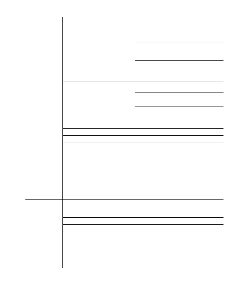
Table 18—Heating Sen/ice Analysis Chart
SYMPTOM
CAUSE
REMEDY
Pilot will not light.
No spark at electrode
Check air gap between electrode tip and pilot target.
Gap should be as shown in Fig. 11.
Readjust as necessary.
Clean moisture or dirt accumulation on electrode
ceramic with cloth.
Cracked ceramic—replace pilot electrode assembly.
Check for loose or broken wiring at and between electronic
control head and electrode. Replace wire or
tighten connection as necessary.
Check fuses or circuit breaker to insure voltage
to unit.
Check for 24-volts between 2 and GR,
and between 6 and GR. If you read 24
volts and above steps have been
completed, replace electronic control
head portion of control head/gas
valve assembly.
Spark shorting out to main burner
Realign electrode tip away from main burner
but maintain spark gap to pilot burner. See Fig. 11.
No gas at pilot burner
Clean pilot orifice.
Check inlet pressure to gas value.
Recommended operating pressure 7-in. w.c.
natural gas, 11-in w.c. LP gas. 0.5 psig
(14-in w.c.) max. pressure
Check for 24 volts between terminals 1
and GR. If you read 24 volts and
above steps have been completed,
replace gas valve portion
of control head/gas valve assembly.
Burners will not ignite.
Water in gas line
Drain—install water trap.
No power to furnace
Check power supply, fuses, wiring, or
circuit breaker.
No 24-volt power supply to control circuit
Check transformer—replace if necessary.
Miswired or loose connections
Check all wiring and wirenut connections.
Dirty pilot—yellow flame
Clean pilot orifice.
Pilot burning improperly—sharp blue flame
Replace pilot.
Burned-out heat anticipator in thermostat
Replace thermostat.
No gas at main burners
1. Check for 24 volts between terminals 3
and GR on control head. If you read 24
volts, replace gas valve portion of
control head/gas valve assembly.
2. If 24 volts is not present, check
flame sensor for cracked ceramic
insulator or shorted sensor cable.
3. Use flame simulator Y99AW-1 to
test sensing circuit. Follow instructions
packaged with simulator.
Replace electronic control if sensor
circuit is not defective.
Broken thermostat wire
Run continuity check to locate break.
Inadequate heating
Dirty air filter
Clean or replace filter as necessary.
Gas input to furnace too low
Check gas pressure at manifold. Clock gas meter
for input. If too low, increase manifold
pressure, or replace with correct orifices.
Unit undersized for application
Replace with proper unit—or add additional unit.
Restricted airflow
Clean or replace filter—or remove any restriction.
Blower speed too low
Use faster speed tap—or install optional blower.
Limit switch cycles main burners
Dirty air filters-clean or replace.
Registers closed, restricted ductwork—open
or remove restriction.
Check heat anticipator setting on thermostat—readjust.
Poor flame
characteristics
Incomplete combustion results in:
Aldehyde odors, (CO), sooting flame—
floating flame
Check all screws around flue outlets and burner
compartment—tighten.
LACK OF COMBUSTION AIR.
Cracked heat exchanger—replace.
Overfired furnace—reduce input, or change orifices.
Check vent for restriction—clean as required.
Check orifice to burner alignment.
23