Carrier 5H User Manual
5f,h, Compressors and condensing units, Installation instructloos
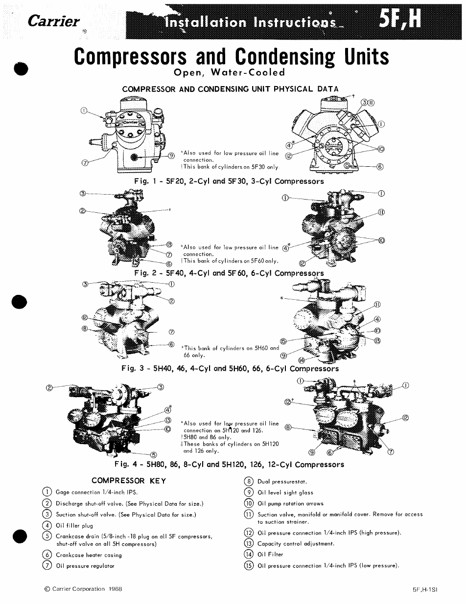
Table of contents
Document Outline
- Open, Water-Cooled
- COMPRESSOR AND CONDENSING UNIT PHYSICAL DATA
- Fig. 1 - 5F20, 2-Cyl and 5F30, 3-Cyl Compressors
- Fig. 2 - 5F40, 4-Cyl and 5F60, 6-Cyl Compressors
- Fig. 3 - 5H40, 46, 4-Cyl and 5H60, 66, 6-Cyl Compressors
- Fig. 4 - 5H80, 86, 8-Cyl and 5H120, 126, 12-Cyl Compressors
- COMPRESSOR KEY
- INSPECT SITE
- Machine Room Temperature and Ventilation -
- PREPARE FOUNDATION
- INSPECT UNIT
- COMPRESSOR INSTALLATION
- Compressor on Steel Base and Support Stand -
- Compressor Bolted to Concrete Base - See Fig. 8.
- Fig. 11 - Wiring Schematic Single Pumpout Cycle
- Table 10 - 5F,H Compressor Crankcase Heater Package
- Table 11 - Crankcase Heater Relay (60-Cycle)
- COMPRESSOR OPERATION
- íttiíítedxaTeíy aíter ¿starting: cort^eascr.
- Fig, 12 - Correct Belt Alignment
- REFRIGERANT PIPING
- CONDENSER WATER PIPING
- LUBRICATION
- REFRIGERANT CHARGING