Carrier 5H User Manual
Page 8
Attention! The text in this document has been recognized automatically. To view the original document, you can use the "Original mode".
Oil Filter should be replaced after 50 hours opera
tion and whenever oil is changed or becomes dirty.
Oil Separator (Optional) - Install separator so its
weight is carried by supports or hangers and not
piping.
Connect
separator
inlet
to
compressor
dis
charge and separator outlet to condenser. Con
nect oil return line (1/4-inch or 3/8-inch copper
tubing) between separator and compressor crank
case. Make line long enough to be flexible and free
from strain. Connect oil return line to upper oil
and gas equalizer line connection (if available) on
compressor. When two compressors are installed
in parallel, connect oil return line to oil equalizer
line between the two compressors. Install shut
off valve in oil return line to facilitate service and
minimize refrigerant loss.
An additional oil charge is required when an
oil separator is used. Watch oil level and check
separator
float
valve
operation
during
initial
compressor
operation.
Follow
instructions
fur
nished with oil separator.
Compressor Muffler (Optional) - Mufflers are in
cluded in condenser piping packages for all 5H
condensing
units.
They
are
recommended
for
all
remote
installations.
Install
mufflers
either
hori
zontally or vertically (refrigerant flow downward).
Arrow on muffler indicates flow direction. Place
outlet at bottom in horizontal installations to pre
vent trapping oil. Locate muffler as close as pos
sible to compressor.
Special Handhole Cover Plates (Optional) have
tapped holes for connecting equalizer lines. When
operating
compressors
in
parallel,
replace
stan
dard covers with special covers. See Fig. 13.
5H120 AND 126 - Tapped cover plate is standard
on 5H120 and 126 compressors. Use only lower
connection for oil equalization. Connect gas equal-
GAS EQUALIZER
■
CpiMNECTION
- j . .
|| OD FLANGE
--CC
Ì
OIL EQUALIZER
CONNECTION
I" IPS
.-.1 i
Fig. 14- Equalizer Connections
(5H120 and 126)
ization line at flange connection. See Fig. 14.
Mating flange for 1-1/8 inch OD is Mueler part
no. A-515; gasket no. A-5152.
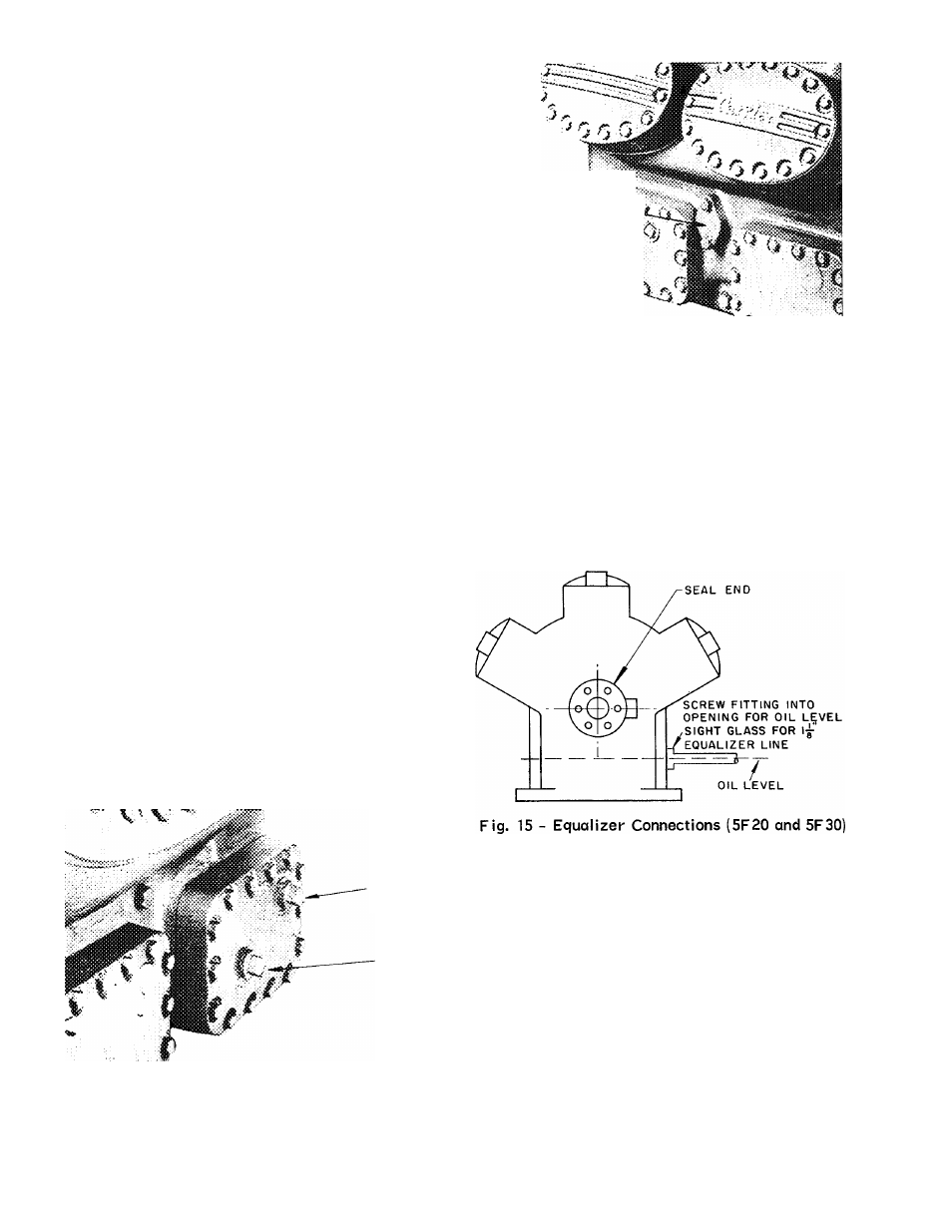
5F20 AND 30 compressors have no special tapped
cover plate. Use opening for oil sight glass with
1-1/8-inch line for gas and oil equalization. For
additional equalization, run a 3/8-inch line to oil
fill plug. See Fig. 15.
GAS
EQUALIZER
CONNECTION
OIL
EQUALIZER
CONNECTION
Fig. 13 - Special Handhole Cover
with Equalizer Connections
Cooled Heads - When used, install water-cooled
heads and piping as shown in Fig. 16.
5F20,30,40,60;
5H40,46,60,66,80
AND
86
com
pressors have one water circuit piped to flow in
either direction. See Fig. 16.
5H120 AND 126 compressors have two parallel
circuits with two 1/2-inch IPS water inlet con
nections and one 1/2-inch IPS water outlet con
nection. See Fig. 16.
Install manually operated valve in each water
circuit, adjusted for 100 F maximum leaving water
temperature.