Inspect site – Carrier 5H User Manual
Page 2
Attention! The text in this document has been recognized automatically. To view the original document, you can use the "Original mode".
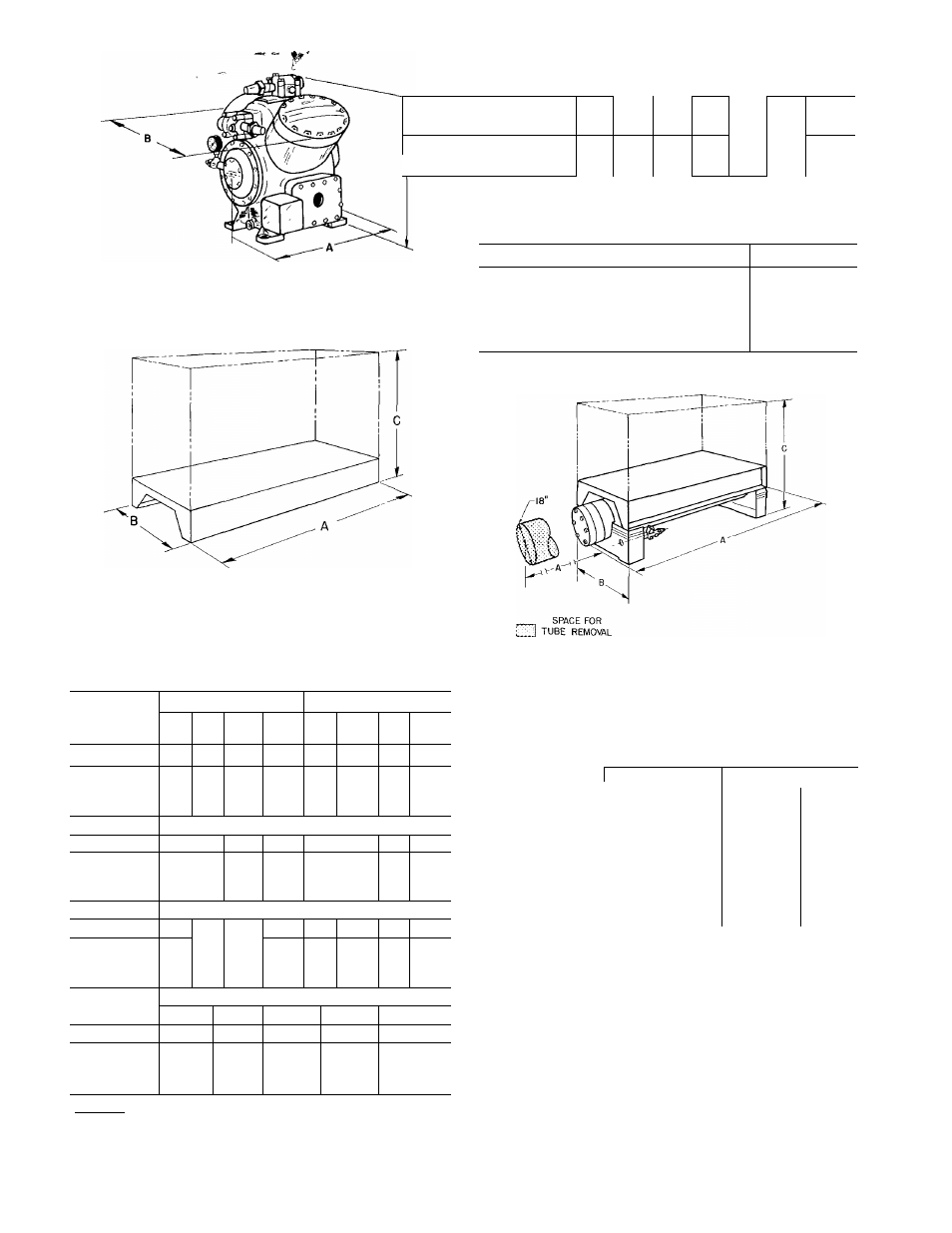
Fig. 5 - Bare Compressor
Fig. 6 - Belt Drive, Direct Drive and
Duplex Compressor Unit
Table 1 - Compressor Physical Data
BARE (Fig. 5)
COMPRESSOR
5F
5H
20
30
40
60
40,
46
60,
66
80,
86
120,
126
WT (lb)
175
215
355
400
610
795
1115 1580
DIM. ^
(ft-in ) “
1-3V,
1-6%
1-6%
1-6
1-8%
1-6
1- 9%
1- 7
1- 8%
1-11%
1- 9
2- 0%
2-6%
2-0%
2-5
2- 7%
2- 3%
2- 5%
3-7%
2-0%
2-8
3-11
2- 3%
2-10%
BELT DRIVE* * (Fig 6)
WT (lb)
260 i 300-
515
600
915 1 Î095
1650 2215
DIM ^
(ft-in.) ^
c
3-2 !3-3
1-
9%: 1-9%
2-
5 (2-4%
3- 9%
2- 2%
2- 1%
3- 9%
2- 2%
2- 6%
4-8%| 4- 9%
2-8%| 2-10
3-l%j3- 2%
5-6%
3-9%
3-6%
5- 7%
3-11%
3- 4%
DIRECT DRIVE (Fig 6)
WT (lb)
-
-
m
3-11%
1- 9%
2- 1%
565
880
1065
О7ОЫ
2210
DIM p
(ft-in.) “
-
4- 0%
1- 9%
2- 6%
4-9%
2-0%
3-1%
4-10%
2- 3%
3- 3%
6-4
2-
7%
3-
7%
6- 7'.,
2- 7%
3- 9%
COMPRESSOR
5H DUPLEX (Fig. 6)
40/60
60/80
80/80
80/120
120/120
WT (lb)
2210
2713
3225
3840
4305
A
DIM 3
(ft-in.)
8-7%
2-8%
3-4%
9-2%
2-8%
3-6%
10-10%
2- 8%
3- 6%
11-5%
2-8%
3-9%
11-10%
2- 8%
3- 9%
;
1 Compressor units (except 5H80) with slightly different
dimensions and horsepower requirements are available to accom
modate oversize condensers and motors See certified prints for
dimensions.
*Belt drive units not available for 5H46,66,86 and 126 sizes
L
Table 2 - Compressor Connections
COMPRESSOR
20
5F
^30] 40
60
40,46'^60,66
5H
80,86
120,126
CONN. Suet
1-1/8
1-5/8
2-1/8 2-5/8 3-1/8 3-5/8
4-1/8
C (in. OD) Disch
7/8
1-3/8
1-5/8 2-1/8 2-5/8 3-1/8
3-5/8
Table 3 - Min Rpm for Capacity Control
and Lubrication
COMPRESSOR
RPM
5F20
600
5F30
700
5F40; 5H40,46; 5H40/60
800
5F60; 5H60,66,120,126; 5H120/120
900
5H80,86; 5H60/80,80/80,80/120
1100
EITHER END
Fig. 7- Direct Drive, Belt Drive Condensing Unit
(Table 5)
Table 4 - Condenser Water Connections
(in. FPT)
MAX PASSES
MIN PASSES
In and Out
In*
Out
1/2
1/2
11
3/4
3/4
11
1-1/4
1-1/4
1-1/2
2
2
2-1/2
2
2
3
2-1/21
2-1/21
41
3t
31
51
CONDENSER
5F20
5F30
5F40,60
09RH027
09RH043,054,070
09RH084,097
09RH127
*Two connections required.
tMPT
UPS
INSPECT SITE
Provide Clearance for removing cylinder heads
and valve plates. Allow space on pump end for
crankshaft
removal.
Space
for
5F20,30,40,60,
5H40,46,60 and 66 is 20 inches; for 5H80,86,120
and 126, 30 inches.
Space at end of condenser must be equal to
length
of
condenser
to
facilitate
tube
removal
and cleaning.