Condenser water piping, Lubrication – Carrier 5H User Manual
Page 9
Attention! The text in this document has been recognized automatically. To view the original document, you can use the "Original mode".
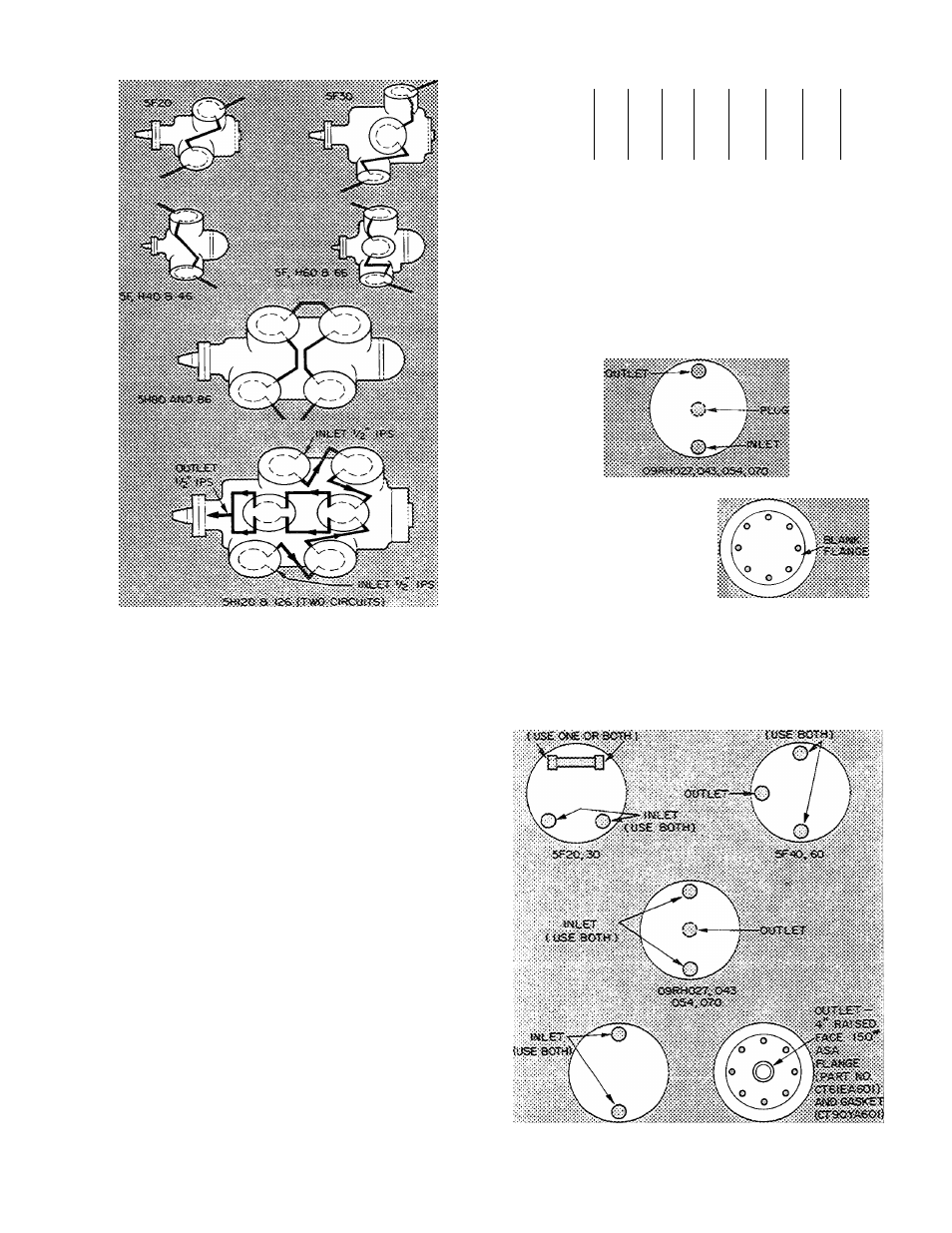
Table 12 - Compressor Oil Charge
Fig. 16 - Schematic Piping for
Water-Cooled Heads
COMPRESSOR
5F20 5F30 5F40 5F60
5H40,
5H46
5H60,
5H66
5H80,
5H86
OIL CHG (pt)
5
5-1/2
12
13
18
21
41
erri mres
itec.
f '
Sr2e>aci
O'
5H120,
5H126
81
8UiS-^0
QiiilSA—y^ “~0
/
N
111
cîîifî>'0a>ii>e3?>Kï7
Fig. 17 - Condenser Maximum Pass Connections
CONDENSER WATER PIPING
Piping - Use piping for maximum pass operation,
Fig. 17, when ample water pressure is available.
Use minimum pass operation. Fig. 18, for low
water pressure or when cooling tower is used.
Water Regulating Valve Adjustment - Set shut-off
point at least 10 F below condensing temperature
to be maintained at maximum load, but not above
90 F. Select shut-off point high enough to close
valve when unit is not operating.
LUBRICATION
Compressors are charged with oil at the fac
tory. Oil quantities are given in Table 12.
Maintain oil level at center of sight glass.
When adding oil, use only a dehydrated, wax-
free refrigeration grade oil of suitable viscosity.
Compressors
are
charged
with
refrigeration
grade oil (Carrier No. PP36) for evaporator tem
peratures above -45 F. When evaporator tempera
ture is -40 or below, replace oil with Carrier
No. PP33.
WfiMAt. ON COOLiMG TOWSfi;
oas«os4.^as7, iz?
Fig. 18 - Condenser Minimum Pass Connections
1072