Table 11 - crankcase heater relay (60-cycle), Compressor operation, Íttiíítedxateíy aíter ¿starting: cort^eascr – Carrier 5H User Manual
Page 7: Fig, 12 - correct belt alignment, Refrigerant piping
Attention! The text in this document has been recognized automatically. To view the original document, you can use the "Original mode".
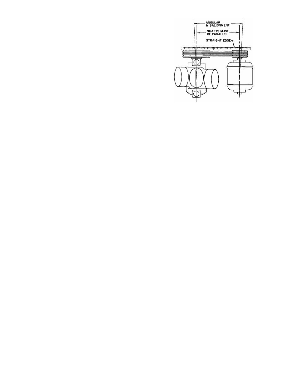
Table 10 - 5F,H Compressor Crankcase
Heater Package
COMPRESSOR
5F20,30,40,60
5H40,46,60,66
5H80,86,120,126
ELECTRICAL
CHARACTERISTICS
Volts Watts
115
230
115
230
115
230
100
100
200
200
200
200
PACKAGE NUMBERS
-5-F—20---------381
-5-F—20---------391
-5-H—40-------- 381
-5-H—40-------- 391
-5-J__40-------291
-5-J—40------- 291
Table 11 - Crankcase Heater Relay (60-Cycle)
CONTROL CIRCUIT VOLTAGE
115
208/230
PART NUMBER
HN61AJ-101
HN61AJ-108
COMPRESSOR OPERATION
Motor Rotation - Start motor before connecting to
compressor. Rotation direction must be same as
arrow cast on pump cover or plate attached near
pump end bearing housing. To rotate compressor
in opposite direction the manually reversible oil
pump must be reversed as follows:
5H120 AND 126; ALL 5F COMPRESSORS - Remove
6 capscrews from oil pump cover. Do not damage
gasket. Rotate cover 180° and replace. Arrow will
now be on top and show new direction of rotation,
5H40,46,60,66,80 AND 86 COMPRESSORS - Drain
oil below level of end bell cover. Remove end bell
assembly and pump end cover. Rotate cover 180°
and replace. Reverse direction of external arrow
(shows compressor rotation without removing end
bell). Arrow on pump end cover must match arrow
on main bearing housing. Replace end bell and
refill with specified oil.
CAifTJON* it
b&twsen oli putnp
cowr stsi oil ï«tnî*> IS- àaîîaagôd, relace xt'with
correct gasket onJy. Check oïî ^CÊinp rotor esá
■ cîearaixce í
Checktcéí ■ ísresstfre
íttiíítedxaTeíy aíter ¿starting: cort^eascr.
Oil Safety Switch installation instructions are in
cluded in Oil Safety Switch Packages.
Motor Fastening Set supplied with all compressor
units (except 5F20,30) includes motor blocks and
shims
for
motor
alignment;
capscrews,
plate
washers and lock washers for fastening motor to
base; taper dowel pins for securing motor position
on
base
(after
alignment);
beveled
washers
for
fastening unit base to vibration isolators or floor.
Install and Align Belt Drive — Clean motor and
compressor
shafts,
flywheel
and
motor
pulley
bores with fine emery cloth.
Install motor pulley, flywheel and keys tightly
on shafts.
Slide motor forward on rails to install belt. Line
up flywheel and motor pulley with a straight edge
Fig, 12 - Correct Belt Alignment
or string (Fig. 12) or by placing a round rod in belt
grooves. Slide motor pulley on shaft to correct any
parallel
misalignment.
Loosen
motor
hold-down
bolts and turn motor frame to correct any angular
misalignment.
Move motor backward with adjusting bolts to
tighten belts. Tighten belts just enough to prevent
slippage.
Determine belt tension by (a) loosening belts
until they slip when motor starts (belt squeals),
then
tighten
enough
to
eliminate
slippage,
(b)
amount belt is depressed at center of span (heavier
belts deflect approximately 1 inch for a 24-inch
span; lighter belts or longer span deflect propor
tionately more)
Install Direct Drive — Instructions for installation
are in the coupling package
Securing Motor to Base — Align motor and
compressor. Drill and ream two holes thru motor
feet and base. Secure motor to base with two
#6 X 2-1/2 taper dowel pins provided in motor
fastening
set.
Locate
holes
diagonally
opposite
motor feet. Use 9/32-inch diameter drill and #6
taper reamer.
REFRIGERANT PIPING
Refer to Carrier System Design Manual, Part
3 for proper piping techniques.
Venting - Replace vent plugs (front and rear heads)
and drain plug (front head) with nipples and valves
if frequent draining of condenser (water side) is
desired.
Refrigerant Drier - See System Design Manual,
Part 3, Page No. 3-75.
Felt Filter - Install felt filter (supplied with com
pressor) in suction line screen. Remove after 50
hours of compressor operation. If dirty, clean with
kerosene or neutral spirits and replace for another
50 hours operation. If filter is clean, leave it out.
Indicate on tag that filter has been cleaned and
reinstalled.
569