Compressor bolted to concrete base - see fig. 8, Fig. 11 - wiring schematic single pumpout cycle – Carrier 5H User Manual
Page 6
Attention! The text in this document has been recognized automatically. To view the original document, you can use the "Original mode".
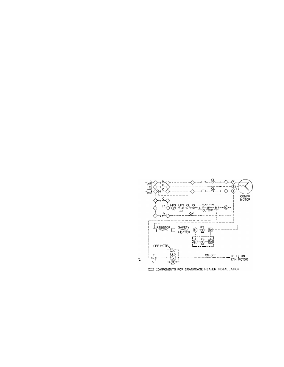
Table 9 - Dimension "C" (ft-in.) (Fig. 10)
CRANKCASE HEATER
COMPR
5F
5H
20
30
40
60
60*
40
46
60
66
60*
66
*
80
86
120
126
DRIVE
Belt
2-8-3/8
2- 8-3/8
3- 7-7/8
3- 7-7/8
4- 2-3/4
4-2-3/4
4-7-3/4
4-7-3/4
J
Direct
3-7-7/8
3- 7-7/8
4-
2-3/4
4-2-3/4
4-2-3/4
4-2-3/4
4-2-3/4
4-5-1/2
4-
5-1/2
5-
9-3/4
5-9-3/4
5-9-3/4
5-9-3/4
*Overs
bas
Loosely
connect
compressor
discharge
line
and adjust condenser position so discharge line
is in line with condenser inlet. Assemble discharge
lines
for
5H
Series
compressors
as
shown
on
special
diagram
sheet
included
in
5H
condenser
piping packages. Before making joints, try coup
ling or belt guard to ensure piping clearance.
Place strips of Fabrica provided between lower
support straps and condenser. See Fig. 10.
Tighten lower strap enough to lift condenser
off stands.
Sweat discharge line to condenser. Adjust con
denser position as required to prevent distortion
of discharge line. Instructions are included in the
piping assembly package.
Place
Fabrica
strips
(see
Fig.
10),
between
condenser and upper straps. Tighten strap bolts
to secure condenser to stand. NOTE; Use lower
straps only for 5F20 and 30 units. Place the two
extra strips of Fabrica between top of condenser
and base. Assemble discharge line as described
above.
Compressor Bolted to Concrete Base - See Fig. 8.
Set compressor level on foundation bolts. (Level
in two directions.) Removal of discharge shut-off
valve exposes face of mounting flange on com
pressor which can be used as a leveling pad. Lo
cate and level motor slide rails. Provide for 3/8
inch to 1/2 inch grout. Tighten foundation bolts
handtight. Do not use wrench.
Wet top of concrete, pour grout and tamp to
fill all spaces between machinery and concrete.
Allow grout to dry slightly then trowel smooth.
Suggested mixture for grout is one part Port
land cement to two or three parts of sharp sand.
Tighten foundation bolts moderately tight when
grout has hardened for 24 to 36 hours. Overtight
ening bolts may cause compressor misalignment.
Energizing crankcase heater helps prevent oil
and refrigerant from mixing and accumulating in
crankcase when compressor is off.
Wire heater to relay or set of normally closed
contacts in compressor starter so it will be de
energized when compressor is operating.
Installation of Heaters- Remove rubber plug from
crankcase heater casing (see Fig, 1 thru 4).
Insert
heater
element
entirely
into
casing.
Element should fit snugly, not loosely.
Wire in accordance with local codes and dia
gram (Fig. 11).
Relay Coil voltage is determined by control cir
cuit voltage which must be specified when ordering
relays.
Mount relays vertically.
When crankcase heater is installed, system can
operate on a single pumpout cycle as shown in
schematic. Fig. 11.
Crankcase heater packages are given in Table
10 and corresponding relay is in Table 11. When
two heaters are usedona 5H80or 120 compressor
only one relay is required.
NOTE; Auto-suction stop valve (flooded systems only)
c
— Compressor
□
CH
— Crankcase Heater
HPS — High Pressure Switch
o
LLS
— Liquid Line Solenoid
EPS — Low Pressure Switch
OL
- Overload
0
PS
— Pressure Switch
R
- Relay
T
— Thermostat
—
Terminal Connections,
Marked
Component Connection,
Unmarked
Component Connection,
Marked
dd W iring
Fig. 11 - Wiring Schematic Single Pumpout Cycle