Carrier 48GH User Manual
Page 7
Attention! The text in this document has been recognized automatically. To view the original document, you can use the "Original mode".
1. Make all electrical connections in accordance
with National Electrical Code and local elec
trical codes governing such wiring.
2. Use only copper conductor for connections
A
between field-supplied electrical disconnect
™
switch and the unit. Do not use aluminum or
copper-clad aluminum wire.
3. Ensure that high-voltage power to unit is within
operating voltage range indicated on unit rating
plate. On 3-phase units, ensure that phases are
balanced within 2%. Consult the local power
company for correction of improper voltage
and/or phase balance.
4. Insulate low-voltage wires for highest voltage
contained
with
conduit
when
low-voltage
control wires are run in same conduit as high-
voltage wires.
5. Do not damage internal components when
drilling thru any panel to mount electrical
hardware, conduit, etc.
6. Make sure that service conductors used between
the electrical service panel and field-supplied
electrical disconnect switch do not have a current
capacity less than the copper wire specified, and
do not create a total voltage drop in excess of 2%
of rated voltage of the unit.
NOTE; When using aluminum conductor from
electrical service to disconnect switch (where local
codes permit use of aluminum wire), make the
connections in accordance with National Electrical
Code. Prepare all aluminum wire immediately be
fore installation by “brush-scratching” the wire,
then coating the wire with a corrosion inhibitor
(such as Pentrox A). Be sure that entire connection
is completely covered to prevent an electrochemical
reaction that will cause the connection to fail very
quickly. Do not reduce effective size of wire by
cutting off strands to fit wire into a connector.
Always use properly sized connectors.
HIGH-VOLTAGE CONNECTIONS ~ Unit must
have a separate electrical service with a field-
supplied, waterproof, fused disconnect switch per
NEC mounted at, or within sight of, the unit. Refer
to unit rating plate for maximum fuse size and mini
mum circuit amps (ampacity) for wire sizing. Table 2
shows recommended wire sizes and lengths based
on rating plate data.
The field-supplied disconnect switch box may be
mounted on unit over the high-voltage inlet hole
in control corner panel. See Fig. 1.
WARNiNG: Label part no. .A-74Í91B, w'hich is
shipped loose in bag of parts, must he affixed to
the disconnect switch box. This label states:
“DO
NOT
DiSCONNECT
THE
ELEC
TRICAL POWER TO THÍS APPUANCE
WITHOUT FIRST TURNING OFF THE
GAS SUPPLY.”
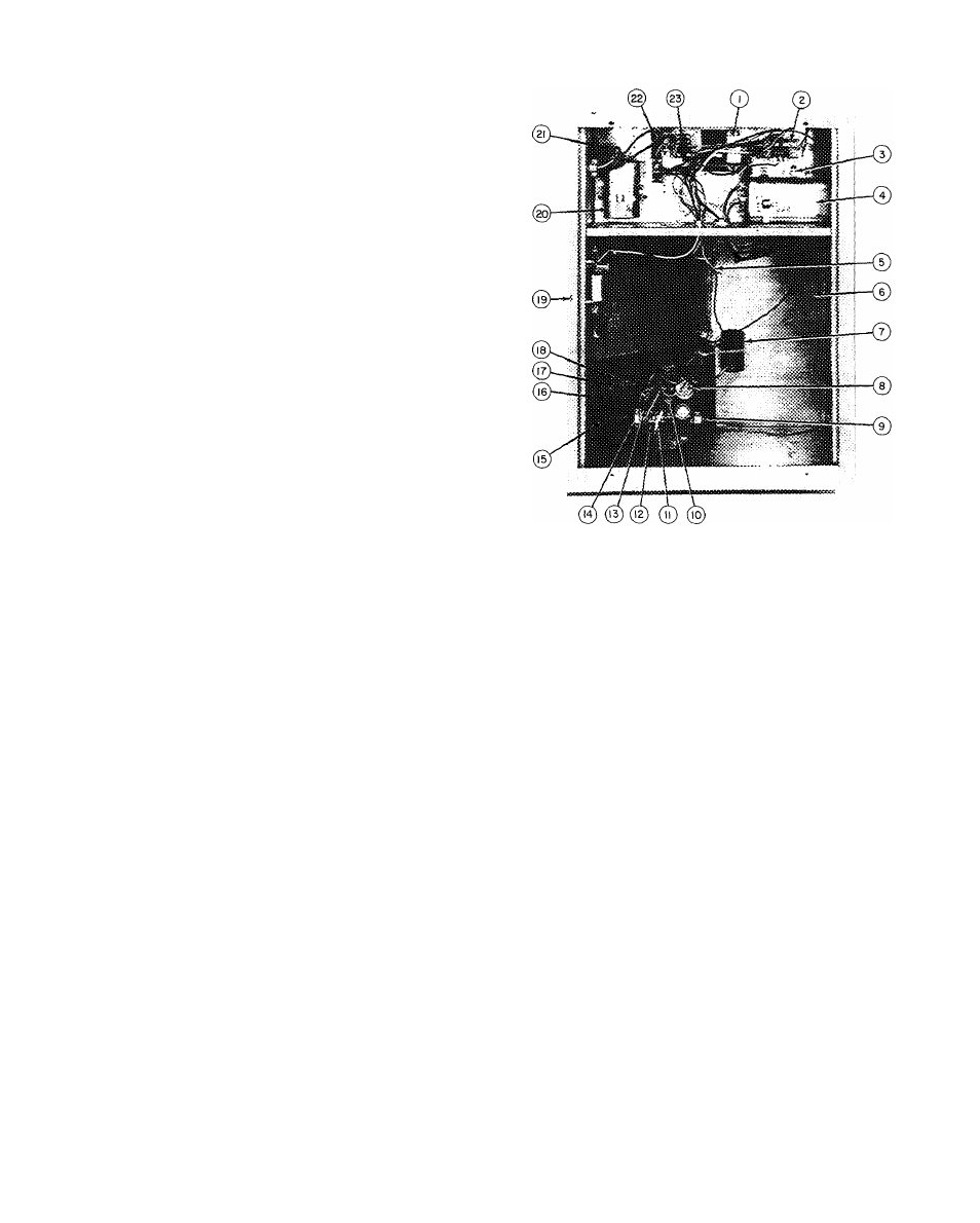
1 — Control Transformer
2 — Compressor Contactor
3 — Ground Lug
4 — Dual Run Capacitor
(for compressor and
condenser fan motor)
5 — LowWoltage Pigtail
Leads
6 — Compressor/Control
Compartment Divider
Panel
7 — Igniter Module
8 — Manual On/Off Knob
9 — Gas Valve Inlet
10 — Pipe Plug —
LP (Propane) unit
pressure switch
mounts here
1 1
1 2
13
14
15
16
17
18
19
20
21
22
23
Pilot Tube
Model 646A-X
Gas Valve
Pressure Tap Pipe Plug
Gas Valve Outlet
Gas Manifold
Gas Burner
Burner Air Shutter
Secondary-Air Shield
Blower Housing
Evaporator Motor
Run Capacitor
Blower/Control
Compartment Divider
Panel
Heating Relay
Cooling Relay
Fig. 6 — Model 48GL036 — Side View
(Partial) with Access Doors Removed
Proceed as follows to complete the high-voltage
connections to unit:
1. Connect ground lead to chassis ground connec
tion when using a separate ground wire.
2.
Run high-voltage leads with field-supplied
conduit into unit control box and connect to
contactor. See unit wiring label, and Fig. 6
and 7.
NOTE: On 3-phase units, connect third high-voltage
lead to brown high-voltage pigtail lead. See unit
wiring label and Fig. 7.
SPECIAL PROCEDURES FOR 208-V
OPERATION
W''ARNiNG: Make sure that power supply to
unit is .switched OFF before making any wiring
changes.