Safety considerations, Introduction, Ímportant – Carrier 48GH User Manual
Page 2: Read before imstailino, General, Installation rigging and unit placement, Safety considerations introduction, Rigging and unit placement -3
Attention! The text in this document has been recognized automatically. To view the original document, you can use the "Original mode".
age
5
5-8
-16
-17
-20
-22
SAFETY CONSIDERATIONS
Installation, start-up and servicing of this equip
ment can be hazardous due to system pressures,
electrical components and equipment location
(roofs, elevated structures, etc.).
Only trained, qualified installers and service
mechanics should install, start-up and service this
equipment.
Consult the Owner’s Manual for routine main
tenance. All other operations should be performed
by trained service personnel.
When working on the equipment, observe pre
cautions in the literature, tags, stickers and labels
attached to the equipment and to any other safety
precautions that apply.
• Follow all safety codes.
• Wear safety glasses and work gloves.
• Use care in handling, rigging and setting bulky
equipment.
WABMiHG'. iiot discoiiEsect elecirio power
io app^atice
first tSTputg off thegas
sappiy. Be sitr-e power to equipitaent is shut off
beibre peifomtijig tnaintenaoce or service.
INTRODUCTION
Models 48GH/GL Packaged Gas/Electric Units
are fully self-contained, combination gas-heating/
electric-cooling units designed for outdoor installa
tion either on a rooftop or ground-level slab. See
Fig. 1.
These units are equipped with an energy-saving
automatic intermittent electric spark ignition system
that does not have a continuously-burning pilot.
Also included are Time Guard II and crankcase
heater for added compressor protection. All units
are manufactured with natural gas controls.
Models 48GH/GL are A.G.A. design-certified
with 2 input ratings. See Table 1. All units are
manufactured for operation at the minimum rating.
For operation at the maximum ratings, optional
burner orifices must be field installed. See Table 3.
These units are factory charged with R-22 refrig
erant. To install: connect gas supply, air ducts, high-
and low-voltage wiring, condensate drain, and
install a field-supplied air filter in the return-air
ductwork.
All units can be connected into existing duct
systems that are properly sized and designed to
handle an airflow of 350 to 450 cfm per each 12,000
Btuh of rated cooling capacity. See Tables 1 and 4
for cooling and heating airflow requirements.
NOTE: When installing any accessory item, see
Installation
Instructions
packaged
with
the
accessory.
ÍMPORTANT —
READ BEFORE IMSTAiliNO
L This isistallation must conforixt witb all
applicable local and nadoaal codes,
2. Power supply (volts, hertz asd phase) musí
correspond to that specified on unit rating
platCv
3.
Electrical supply provided by utility ^
suiScient to handie load Imposed by this unit.
4. Refer to the 48GB/GL dimensional dtawing
for locations of gas inlet, elecírícal inlets,
condensate dram, duct connections,, and
required clearances before setting unit 'm
place.
5. Locate the unit where the vent cap wlli be a
minimum of 4 ft from openable windows or
doors.
6. This instaUation must conform w-ith local
budding codes and with the 'Naiional Fnel Gas
Code ANSI Z223.1-^B74.
GENERAL
Models 48GH/GL Packaged Gas/Electric Units
have been designed and tested in accordance with
ANSI Z21.47-1978, ARI Standard 210-79 and ARI
Standard 270-75. The appliance design is certified
by the American Gas Association (A.G.A.) for use
with natural or LP (propane) gases with appropriate
components and orifices.
INSTALLATION
Rigging and Unit Placement
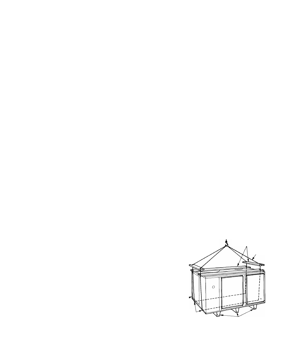
CAUTION: Wh.cn rigjing unit to be lifted, use
spreader bars to protect top and sides. Models
GL must be rigged for iiftiug as shown
iu Fig. 2. Use extreme caution to prevent
damage when moving unit.
SPREADER BARS:
(2)2x4xUNIT LENGTH PLUS I0"WITH
I
f
DEEP
90°
NOTCHES EACH END
(2) 2x4xUNIT WIDTH WITH 1^'
DEEP 90° NOTCHES
EACH END
USE SPREADER BARS
TO PROTECT UNIT
CHAIN
PACKAGED UNIT-
LOCATE CHAINS THRU
HOLES IN BASE
CHANNELS
TWO OR THREE BASE
CHANNELS ATTACHED TO
BOTTOM OF UNIT
Fig. 2 — 48GH.GL Suggested Rigging
1SI