Carrier 48GH User Manual
Page 5
Attention! The text in this document has been recognized automatically. To view the original document, you can use the "Original mode".
€
NOTE: Screw holes in vent stack extension and
unit top are not symmetrically located; thereby
ensuring proper orientation when installing these
components.
Refer to Fig. 4 and install vent cap as follows:
1. Place combustion-air duct over combustion-air
opening in unit top, and line up screw holes in
duct with holes in top. Secure duct to top using
screws with rubber washers (provided).
2. Place gasket and vent stack extension thru hole
in combustion-air duct, orient screw holes in
base of vent stack extension with holes in unit
top, and secure gasket and vent stack extension
to unit top using screws provided.
3. Form flat wire screen (provided) into circular
shape around protruding lip of combustion-air
duct, and bend wire ends thru holes of screen
mesh to secure screen in place. Make sure that
no sharp edges are left exposed.
4. Place vent cap sleeve inside vent stack extension.
Orient spring clip of vent cap with slot in
extension. Be sure that clip snaps into slot to
secure clip onto extension.
Typical Piping
— The gas supply pipe enters unit
thru access hole provided. See Fig. 1 for location.
The gas connection to unit is made to the 1/2-in.
FPT gas inlet on gas valve. See Fig. 6.
Install a separate gas supply line that runs
directly from meter to heating section. Do not use
cast-iron or galvanized pipe. Check local utility for
recommendations concerning existing lines. Choose
a supply pipe that is large enough to keep pressure
loss as low as practical. Never use pipe smaller than
the 112-in. FPT gas inlet on gas valve.
When installing gas supply line, observe local
codes pertaining to gas pipe installations. Refer to
National Fuel Gas Code ANSI Z223.1-1974 in
absence of local building codes. Adhere to pertinent
recommendations.
1. Avoid low spots in long runs of pipe. Grade all
pipe 1 /4-in. in every 15 ft to prevent traps. Grade
all horizontal runs downward to risers. Use risers*,
to connect to heating section and to meter.
2. Support all piping with appropriate hangers, etc.
Use a minimum of one hanger in every 6 feet. For
pipe sizes larger than 1/2 in., follow recom
mendations of national codes.
3. Apply joint compounds (pipe dope) sparingly
and only to male threads of joint when making
pipe connections. Use only pipe dope that is
resistant to action of liquefied petroleum gases
as specified by local and/or national codes.
Never use teflon tape.
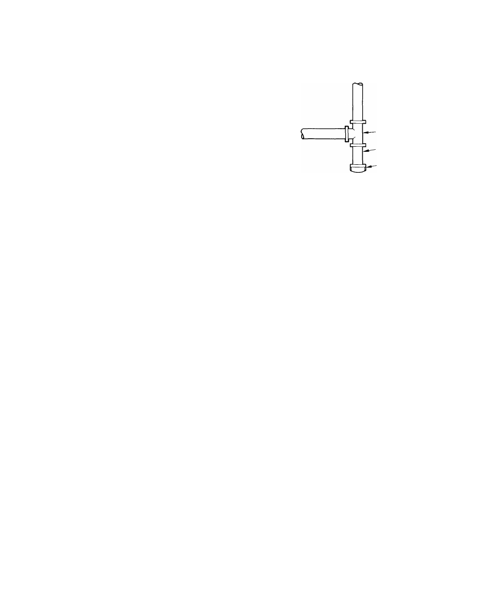
4. Install a sediment trap in riser leading to the
heating section. This drip leg functions as a trap
for dirt and condensate. Install trap where con
densate cannot freeze. Install this sediment trap
by connecting a piping tee to riser leading to
heating section so that straight-thru section of
tee is vertical. See Fig. 5. Then, connect capped
nipple into lower end of tee. Extend capped
nipple below level of gas controls.
-TEE
-NIPPLE
CAP
Fig. 5 — Sediment Trap
5. Install an accessible, external, manual shutoff
valve in gas supply pipe within 6 ft of heating
section. Install a 1/8-in. NPT plugged tapping
that is accessible for test-gage connection
immediately upstream of gas supply connection
to heating section.
6.
Install ground-joint union close to heating
section between gas valve and external manual
shutoff valve.
CAUTION: Unstable operaiton may occur,
parttcüïariy -ander Mgh-wiiKi coiiditions, wh.cn
gas valve and mardfold assembly are forced out
of poskîoo while connecting improperly routed
rigid gas piping to gas valve. Use a backup
wrench when making connection to avoid strain
on, or distortion of, gas control piping.
7. Use flexible gas pipe to make connection between
rigid gas piping and gas valve where permitted
by local codes. Flexible pipe ensures proper
alignment between manifold orifices and burner.
WARNING: Never use a match or other open
Same when, checking for gas leaks.
8. Check for gas leaks at all field-installed and
factory-installed gas lines after all piping connec
tions have been completed. Use soap-and-water
solution (or method specified by local codes
and/or regulations).
Duct Connections
— Model 48GH/GL has duct
flanges on the supply- and return-air openings on
side of unit. See Fig. 1 for connection sizes and
locations.
W'AR-NiNG; The desigaand to.stahatioa.ofduct
system must be in acoordarice with standard&of
National Fire ProtectÎoa Association for
m&tahattou of nopresideace-type air condi-
tiimiag and veutiiatmg systems, NFPA No,
codes atïd ordinances-