Stallation data, Venting – Carrier 48GH User Manual
Page 4
Attention! The text in this document has been recognized automatically. To view the original document, you can use the "Original mode".
3/4-in. galvanized pipe, or
plastie pipe. Do
not undersize the tube. Pitcfi drain tube downward
at a slope of at least 1 in. in every 10 ft of horizontal
run. Be sure to check drain tube for leaks.
Condensate water can be drained directly onto
roof in rooftop installations (where permitted) or
onto a gravel apron in ground-level installations.
When using a gravel apron, make sure it slopes
away from unit.
TO DRAIN
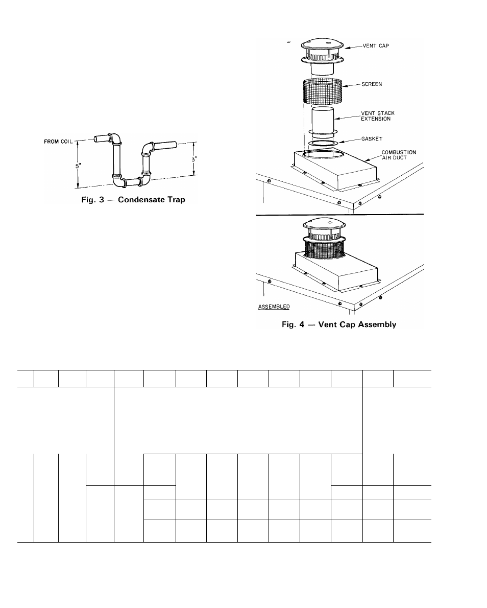
Venting
— The vent-cap and combustion-air duct
assemblies are shipped in either the blower or
control compartment. Remove access doors to
locate assemblies. See Fig. 1 for door locations. Vent
stack extension is shipped either in air hole in unit
top or fastened to back of the control box or in
blower compartment.
CAUTION: Vestiug systetu ss
ea-
s»£« proper ventiijg. Vejit-ci^ assembly tnaslbe
ins.taSed as indicated in this setikm, of Instalia-
tioo liistructtosis.
stallation Data
042
00
GL042
500
GH042
300
GH042
500
GL048
300/310
GL048
500/510
GL048
600/610
GH048
300/310
GH048
500/510
GL060
300/310
GL060
500/510
GL060
600/610
GH060
300/310
GH060
500/510
i- 5-5/8
6- 0-3/8
6- 0-3/8
i-
8-5/8
3- 8-5/8
3- 8-5/8
MO-1/8
4- 6- 1/8
4- 6- 1/8
2- 0
2- 8
2-8
1- 1-1/4
1- 1-1/4
1- 1- 1/4
3- 8-7/8
0- 8-7/8
0- 8-7/8
3- 1-3/8
0- 1- 3/8
0- 1- 3/8
0-10
0-10- 1/2
0-10-1/2
1-10-5/8
2- 0- 11/16
2- 0- 11/16
4- 1
3- 10
4 -1
>72
672
672
672
768
768
768
768
768
951
951
951
951
951
137
437
437
437
499
499
499
499
499
618
618
618
618
618
120
420
440
440
535
535
535
555
555
575
575
605
605
605
130
430
450
450
545
545
545
565
565
585
585
615
615
615
1,000
60,000
80,000
80,000
80,000
80,000
80,000
100,000
100,000
100,000
100,000
100,000
1 20,000
1 20,000
>,000
75,000
100,000
100,000
100,000
100,000
100,000
125,000
1 25,000
1 25,000
1 25,000
1 25,000
150,000
1 50,000
400
1400
1400
1400
1600
1600
1600
1600
1600
1981
1981
1981
1981
1981
) 15
0 15
0 15
0 15
0 20
0 20
0 20
0 20
0 20
0 20
0 20
0 20
0 20
0 20
mum recommended filter areas when these units have been field converted for operation at maximum rated
heating input
.fAll units have a minimum and maximum A G A -certified rated heating input and are manufactured with burner
orifices for heating operation at minimum rating
Units may not be derated below this minim um rating