Condensate disposal, Asse coni loca stac top blo\ c – Carrier 48GH User Manual
Page 3
Attention! The text in this document has been recognized automatically. To view the original document, you can use the "Original mode".
Unit must remain in an upright position during all
rigging and moving operations. Unit must be level
for proper condensate drainage; therefore, ground-
level pad or field-supplied mounting curb must be
level before setting unit in place.
ROOFTOP INSTALLATION
CAUliON: When instalHng nnit on a rooftop^
he sare roof support tits odditionaJ weight.
Refer to Prodìtct Data Digest to ohiaia total
weight aad corner weight Istformailon,
When installing a Model 4»GH/GL end-
discharge unit with a field-supplied downflow
plenum, a field-supplied roof-mounting curb must
be installed on and flashed into roof before unit
installation.
When installing a Model 48GH/GL end-
discharge unit without a downflow plenum, place
unit on a level base that provides proper support. On
flat roofs be sure that unit is located at least 4 in.
above highest expected water level on roof to pre
vent flooding. Consult local codes for additional
installation requirements.
GROUND-LEVEL
INSTALLATION
—
Place
unit on a solid, level concrete pad that is a minimum
of 4 in. thick and that extends approximately 2 in.
beyond casing on all 4 sides of unit. Do not secure
unit to pad except when required by local codes.
CLEARANCES — The required minimum oper
ating and service clearances are shown in Fig. 1.
Condenser fan discharges thru top of unit. En
sure that fan discharge does not recirculate to
condenser coil. Do not locate unit in either a corner
or under a complete overhead obstruction. Mini
mum clearance under a partial overhang (such as a
normal house roof overhang) is 3 ft above vent cap.
Do not locate unit where water, falling ice or snow
from an overhang or roof will damage or flood the
unit. Do not locate unit where grass, shrubs, or
other plants will interfere with airflow either into
or out of unit.
Condensate Disposal
NOTE: Ensure that condensate-water disposal
methods comply with local codes, restrictions and
practices.
Models 48GH/GL dispose of condensate water
thru a 3/4-in. MPT drain fitting. See Fig. 1 for
location.
Install a 3-in. trap at drain fitting to ensure
proper drainage. See Fig. 3. Make sure trap outlet
is at least 2 in. lower than unit drain pan connection
to prevent pan from overflowing. Prime trap with
water.
If the installation requires draining condensate
water away from the unit, connect a drain tube
using a minimum of 7/8-in. OD copper tubing.
3/4
not
at a
run.
C
roo]
ont(
Wh
awa
FROM
Ver
asse
coni
loca
stac
top
blo\
C
S
h
m
tì<
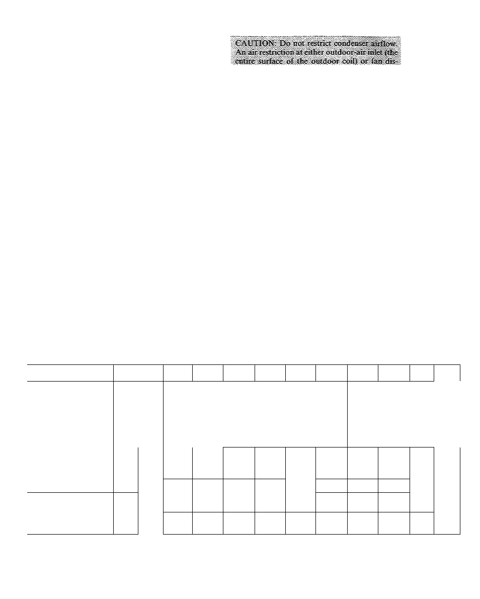
Table 1 — Installation C
MODEL 48
GL018
GL024
GH024
GL030
GH030
GL036
GL036
GL036
GH036
GH036
GL042
GL042
SERIES
300
300
300
300/310
300/310
300/310
500/510
600/610
300/310
500/510
300
500
DIMENSIONS (ft-in )
A
4-5-5/S
4-5- 5/8
5- 5-5/8
B
2-6-3/8
3-4-3/8
3- 8-5/8
c
3-2-1/8
3-5- 1/8
3-10-1/8
D
1- 4
1- 7
2- 0
E
1- 4
1-1- 1/4
1- 1-1/4
F
0-7-1/4
*, 0-8-7/8
0- 8-7/8
G
0-1-3/32
0-1- 3/8
0- 1-3/8
H
0- 11
0-10
0-10
J
1-10-5/8
K
3-7-3/8
4-0-3/8
4- 1
FIELD-SUPPLIED FILTER
SIZE (sq in )•
Standard Disposable Type
289
396
396/433t
522
522
576
576
576
583/722t
583/722t
672
672
Cleanable- or
High-Capacity Type
188
257
257/281t
339
339
374
374
374
379/469t
379/469t
437
437
OPERATING WT (lb)
320
325
375
375
375
380
380
380
475
475
420
420
SHIPPING WT (lb)
330
335
385
385
385
390
390
390
485
485
430
430
HEATING INPUTt (Stub)
Min
40,000
40,000
60,000
40,000
60,000
60,000
60,000
60,000
100,000
100,000
60,000
60,000
Max
50,000
50,000
75,000
50,000
75,000
75,000
75,000
75,000
125,000
1 25,000
75,000
75,000
COOLING AIRFLOW (Cfm)
600
825
825
1088
1088
1200
1200
1200
1215
1215
1400
1400
EXTERNAL STATIC
PRESSURE (in wg)
0 10
0 10
0 10
0 15
0 15
0 15
0 15
0 15
0 15
0 15
0 15
0 15
•Recommended, field-supplied air filter areas shown are based on either cooling airflow at a velocity of 300 ft per
minute or heating airflow at a temperature of 60 F, depending on whichever value is larger Air filter pressure drop
should not exceed 0 08 in wg for unit to produce rated cooling performance
tWhen Models 48GH024 or GH036 are installed for operation at minimum rated heating input, recommended
minimum air filter area is the smaller sq in figure shown for each type of filter Larger figures shown are mini-
mum rei
heating
|AII units
orifices
1