A caution, 5^yel - -s, Table 4—air delivery (cfm) performance – Carrier 50QQ User Manual
Page 6
Attention! The text in this document has been recognized automatically. To view the original document, you can use the "Original mode".
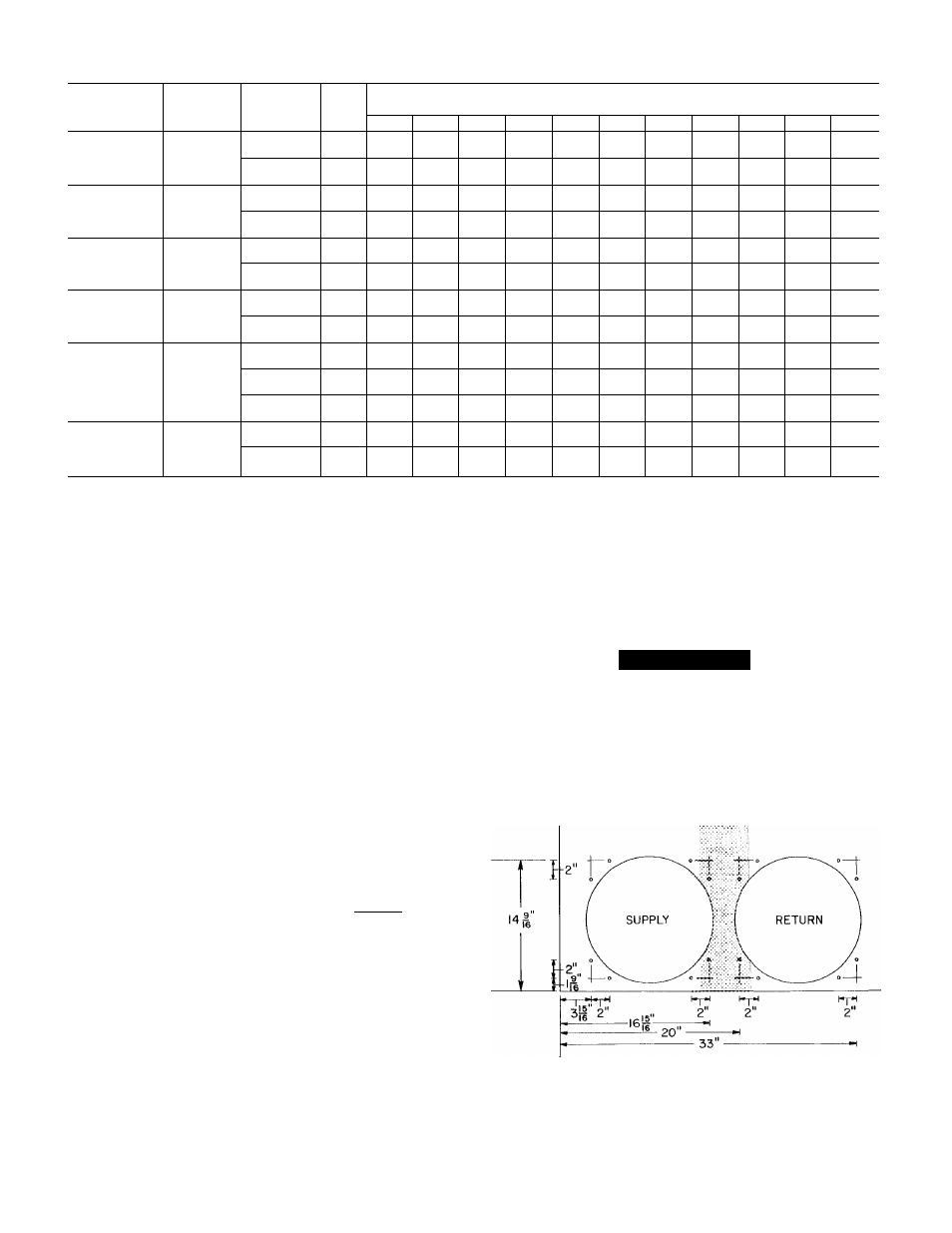
Table 4—Air Delivery (Cfm) Performance
MODEL
50QQ
UNIT
VOLTAGE
BLOWER
MOTOR
SPEED
COIL
EXTERNAL STATIC PRESSURE (in. wc)
0.0
0.1
0.2
0.3
0.4
0.5
0.6
0.7
0.8
0.9
1.0
Low
Dry
___
—
___
___
—
800
730
640
_
—
018-10
230
Wet
—
_
—
—
—
750
680
550
—
—
—
High
Dry
_
—
—
—
—
820
680
550
—
—
Wet
—
—
—
—
785
685
575
—
—
—
Low
Dry
1450
1410
1375
1320
1345
1175
1090
985
850
760
024-10
230
Wet
1390
1340
1290
1225
1165
1105
1020
915
740
_
_
High
Dry
1500
1475
1435
1390
1335
1260
1180
1090
980
840
—
Wet
1460
1405
1350
1295
1255
1190
1110
1020
870
—
—
Low
Dry
___
___
1425
1360
1295
1235
1160
1080
995
925
815
030-
230
Wet
—
—
1380
1315
1250
1190
1125
1045
960
895
790
10&30
High
Dry
___
___
1500
1425
1245
1275
1190
1120
1020
935
830
Wet
—
_
1450
1375
1295
1230
1145
1080
985
905
805
Low
Dry
__
___
1440
1400
1345
1290
1225
1140
1040
930
—
036-
230,
Wet
—
1400
1365
1290
1240
1185
1090
990
890
—
10&30
460
High
Dry
___
___
1500
1460
1410
1345
1270
1195
1075
930
—
042-10
Wet
—
_
1465
1430
1365
1300
1230
1145
1020
890
—
Low
Dry
1850
1810
1770
1725
1685
1640
1600
1535
1480
1410
1345
Wet
1820
1775
1730
1695
1650
1610
1555
1500
1440
1385
1320
042-30
230,
Med
Dry
1960
1915
1885
1830
1780
1725
1655
1600
1540
1470
1400
048-
460
Wet
1895
1880
1850
1795
1745
1690
1620
1565
1510
1445
1375
10&30
High
Dry
2230
2160
2120
2070
2010
1950
1890
1820
1750
1675
1590
Wet
2145
2105
2060
2000
1940
1880
1820
1750
1690
1615
1540
Low
Dry
2395
2365
2335
2290
2245
2205
2150
2100
2050
2000
1915
060-
230,
Wet
2375
2325
2295
2250
2225
2180
2135
2070
2020
1960
1875
10&30
460
High
Dry
2570
2525
2470
2425
2370
2335
2265
2220
2160
2100
2030
Wet
2550
2485
2435
2385
2345
2310
2235
2190
2130
2075
2000
NOTES:
1. Air delivery values are based on 230- or 460-volt unit operating voltage without air filter or optional electric heaters Deduct field-supplied air filter and
electric heater pressure drop to obtain external static pressure available for ducting
2 Dashes indicate portions of table that are beyond blower motor capability,
3 Do not operate unit at a cooling airflow less than 350 cfm for each 12,000 Btuh of rated cooling capacity. Indoor coil icing may occur at airflows below
this point
3. Using duct flange as a template, make sure marked
locations line up with clearance holes on flanges.
4. At marked locations, drill screw engagement holes
using a #26 (.147-in.) twist drill.
GROUND LUG
(IN SPLICE BOX)
I - PHASE
CONN.
TO
DISCONNECT
PER NEC
--GROUND LEAD
L2
__________
__________ ^
BLK
YEL--------1
HEAT PUMP
GROUND LUG
(IN SPLICE BOX)
3-PHASE
CONN.
TO
DISCONNECT
PER NEC
- - GROUND LEAD -
L2----------------------
BLK-------- S
L3
■BLU--------5
-5^YEL - -s
HEAT PUMP
A CAUTION
On 042, 048, do not drill deeper than one inch in shaded
area. Damage to refrigerant coil could result.
5. Attach duct adapters using #10B, V
2
-in. long screws
supplied in accessory kit.
6. Finished kit installation accommodates a 14-in. x 14-in
duct.
A88059
Fig. 7—Line Power Connections
Fig. 8—Duct Fiange Kit Dimensions and Hoie Locations
A88058
ELECTRIC HEATER INSTALLATION-For complete
heater installation data, refer to separate accessory electric
heater Installation, Start-Up and Service Instructions.
#