A warning – Carrier 50QQ User Manual
Page 14
Attention! The text in this document has been recognized automatically. To view the original document, you can use the "Original mode".
Return Air Filter (Field Supplied)—
Replace disposable filter
4 times a year, clean permanent filter a minimum of 4 times
yearly or as required. Flush permanent filter with hot water,
steam or soak in mild solution of soap or detergent and
water. Allow filters to dry and replace. Refer to filter manu
facturer’s instructions, as required, for other types of
filters.
Outdoor Coil—
Inspect outdoor coil regularly. A dirty coil
can lead to premature compressor failure and higher operat
ing costs. If cleaning is required, be sure power to system is
shut off before attempting to clean coil.
Outdoor coil may be cleaned with brush, vacuum cleaner, or
low-pressure water (weather permitting). Do not use indus
trial strength cleaning fluids for cleaning coils. If coil has 2
rows, make coil accessible by removing the top cover and
wash out with garden hose.
A WARNING
Be careful! Coil fins are sharp. Protect hands with
gloves when cleaning or handling coil.
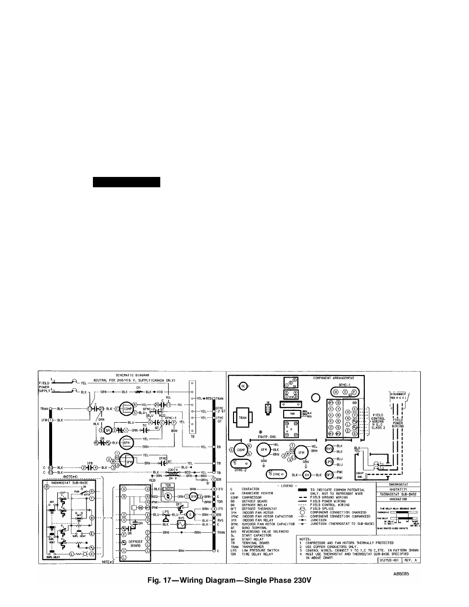
Sequence of Operation (Refer to Figs. 17, 18, 19)—
When
power is supplied to unit, transformer (TRAN) is energized.
If crankcase heater switch (CHS) is closed and outside tem
perature is below 65 F, crankcase heater (CH) will be
energized.
COOLING—On a call for cooling, thermostat makes circuit
R-0, R-Y and R-G. When room temperature rises to within 2
degrees of control setting of thermostat, circuit R-O makes,
energizing reversing vedve solenoid (RVS). Unit is now in
standby condition for cooling. As room temperature rises,
the second-stage bulb makes, allowing a circuit (R-Y)
through low-pressure switch (LPS) to contactor (C), starting
compressor (COMP) and outdoor fan motor (OFM). Circuit
R-G energizes indoor fan relay (IFR) starting indoor fan
motor (IFM).
When thermostat is satisfied, contacts open de-energizing
contactor. Indoor fan relay, compressor and motor stop.
HEATING—On a call for heat, thermostat makes circuits
R-Y and R-G. Circuit R-Y is completed, allowing circuit
through low-pressure switch (LPS) to contactor (C), starting
compressor (COMP) and outdoor fan motor (OFM). Circuit
R-G also is completed, energizing indoor fan relay (IFR) and
starting indoor fan motor (IFM).
Should room temperature continue to fall, circuit R-W is
made through second-stage thermostat bulb. If optional
electric heat package is used, a sequencer is energized bring
ing on first bank of supplemental electric heat. When ther
mostat is satisfied, contacts open, de-energizing contactor
and sequencer. Motors and heaters de-energize.
DEFROST—Defrost board (DB) is a time/temperature con
trol which includes a field-selectable time period between
check if defrost is necessary (30, 50 and 90 minutes). Elec
tronic timer and defrost cycle start only when contactor is
energized and defrost therniostat (DFT) is closed.
Defrost mode is identical to cooling mode except outdoor
fan motor stops and a bank of optional electric heat turns
on to warm air supplying the conditioned space.
14