A caution, Lubrication – Carrier 50QQ User Manual
Page 12
Attention! The text in this document has been recognized automatically. To view the original document, you can use the "Original mode".
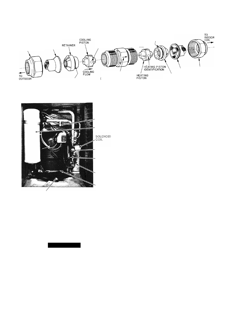
FLARE
NUT
STRAINER
COIL
COOLING PISTON
IDENTIFICATION
RUBBER 0-RING
STAMPED ARROW ON
COUPLING BODY
TOWARD INDOOR COIL)
HEATING
FLOW
RUBBER 0-RING
STRAINER
n
U
t
'^^
RETAINER
A87292
Fig. 11—Metering Device (Dual-Piston) Components
SUCTION
SCHRADER
FITTING
ACCUMULATOR
COMPRESSOR HOLDDOWN BOLT
Fig. 12—Compressor Section
REVERSING
VALVE
DISCHARGE
SCHRADER
FITTING
CRANKCASE
HEATER
SWITCH
CRANKCASE
HEATER
A87293
6. Remove wraparound crankcase heater (if used) from
compressor base.
7. Remove compressor holddown bolts and lift compres
sor out.
8. Carefully unbraze suction and discharge line piping
stubs from compressor. If oil vapor in piping stubs
ignites, use quenching cloth.
A CAUTION
Muffler may contain quemtity of oil.
9. Braze piping stubs (removed in step 8) on new
compressor.
10. Install new compressor in unit. Braze suction and dis
charge lines to compressor piping stubs (at points
where cut, step 5) using field-supplied copper cou
plings. Ensure compressor holddown bolts are in place.
Connect wiring.
NOTE:
Reinstall wraparound crankcase heater (if used)
on compressors.
11. Clean system. Add new suction line filter drier as
described below. Refer to Fig. 10.
NOTE:
If a compressor failure was caused by motor
winding burnout, the byproducts of the burnout must
be separated from the circulating refrigerant. This
must be done before the byproducts enter the reversing
vedve or accumulator emd render peu-ts inoperative.
Burnout byproducts can cause future system operating
problems if left in the system.
Clean the system by installing a suction line drier in
the refrigerant line where the suction gas enters the
reversing valve. During the cooling cycle, this is the
line from the indoor coil running across the top of com
pressor compartment; during heating cycle, install
drier in line between outdoor coil and reversing valve.
If possible, run unit in cooling mode when cleaning sys
tem as installation of temporary suction drier is
simplified.
For drier installation during heating cycle, cut line
between outdoor coil and reversing valve, install fit
tings and tubing, and install suction filter drier. To pro
vide protection for the reversing valve, do not place fil
ter drier between reversing valve and accumulator.
Since the suction drier works in one mode only, tempo
rarily wire the unit in the selected mode (heating or
cooling, based on suction drier location). To ensure
cooling operation only, instiJl a jumper between termi-
neds R and O on the low-voltage terminal board. For
heating operation only, remove and insulate one of the
reversing valve solenoid leads. Run unit for 48 hours
emd check oil for acidity. If satisfactory, remove suc
tion line drier. Refer to and follow procedure under
Metering Device Servicing for cleaning of pistons.
Rewire unit to normal conditions.
12. Triple-evacuate and recharge unit. See Refrigerant
Charging.
Filter Drier—
Install an accessory reversible, liquid line filter
drier assembly, following the instructions in accessory
package.
NOTE:
Follow instructions carefully as piston locations are
reversed from those shown when a filter drier is not used.
Lubrication
COMPRESSOR contains factory oil charge. Replace oil
when lost. See Table 7 for oil recharge. Use Carrier PP33-1,
Texaco Capella WF-32 or Suniso 3GS oil.
#
12