Indoor coil, A warning, Fig. 13—indoor fan – Carrier 50QQ User Manual
Page 13
Attention! The text in this document has been recognized automatically. To view the original document, you can use the "Original mode".
#
FAN MOTOR BEARINGS are prelubricated for 3 years
heavy duty or 5 years normal duty. Oiling holes are pro
vided at each end of fan motor, remove fan motor and lubri
cate motor with 32 drops (16 drops per hole) of SAE 10
nondetergent oil at intervals described below:
a. Annually, when environment is very dirty, ambient
temperature is higher than 105 F and average unit
operating time exceeds 15 hours a day.
b. Every 3 years when environment is reasonably clean,
ambient temperature is less than 105 F and unit oper
ating time averages 8 to 15 hours a day.
c. Every 5 yeeirs when environment is clean, eunbient tem
perature is less than 105 F and unit operating time
averages less than 8 hours a day.
Indoor Coil
A WARNING
Before performing recommended maintenance, be sure
main power switch to unit is turned off. Electrical
shock can cause personal injury or death.
Lift or remove unit top cover for access to indoor coil.
Inspect coil periodically. Clean as described under Outdoor
Coil.
Condensate Drain—
Clean condensate drain trap with bot
tle brush; then flush condensate pan beneath indoor coil
with clean water. Ensure water flows freely through conden
sate drain.
Indoor Fan Assembly (Fig. 2)—
Fan wheel should be cen
tered in fan housing. To adjust fan, remove as follows;
Disconnect fan motor wiring. Remove 6 sheet metal screws
holding fan orifice in place. Remove 3 fan motor bracket
mounting screws. Slide out complete fan, motor and orifice
assembly.
Reassemble in reverse order.
To clean fan wheel and housing, use a brush, warm water
and detergent. Do not splash water on motor.
FAN MOTOR
MOUNTING BOLTS
ORIFICE RING
FAN MOTOR
BLOWER
HOUSING
^
■ Tinflnnir—■ _
CAPACITOR
-CONDENSATE TRAP
Fig. 13—Indoor Fan
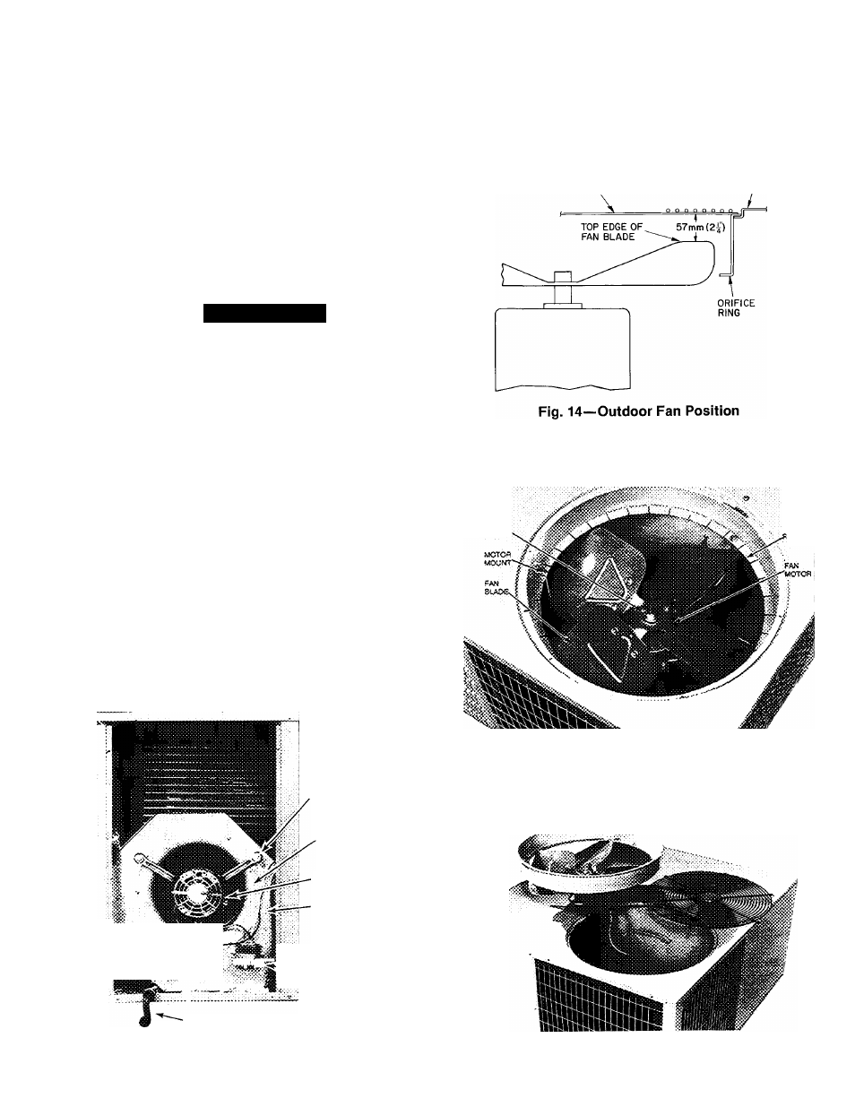
Outdoor Air Fan—
Fan position is shown in Figs. 14 and 15.
Adjust fan by loosening setscrews and moving blades up or
down. To remove outdoor air fan and motor: disconnect
power, and remove screws holding discharge grille in place.
Disconnect fan motor leads from the motor. Lift complete
fan, motor, and orifice assembly (Fig. 16) out of unit. After
replacing fan motor assembly, reconnect fan motor leads.
DISCHARGE GRILLE
TOP COVER
SET.
scae-A
ORIRCÉ
ime
Fig. 15—Fan and Motor
Fig. 16—Fan and Motor Removed
13