Warnock hersey, Step 7 — make outdoor-air inlet adjustments, Fig. 12 — 25% outdoor-air section details – Carrier 50HJ015 User Manual
Page 8: Step 7 — make outdoor-air inlet, Adjustments, Step 8 — install outdoor-air hood, Table 2 — electrical data
Attention! The text in this document has been recognized automatically. To view the original document, you can use the "Original mode".
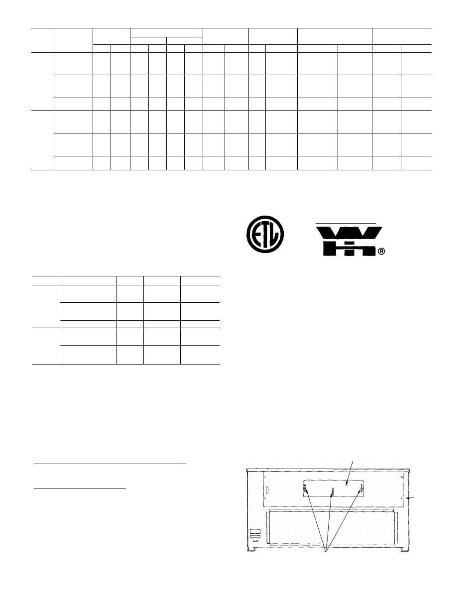
Table 2 — Electrical Data
UNIT
50HJ
V-PH-HZ
VOLTAGE
RANGE
COMPRESSOR
CONDENSER
FAN MOTOR
EVAPORATOR
FAN MOTOR
ACCESSORY/OPTIONAL
ELECTRIC HEATERS*
POWER SUPPLY
No. 1
No. 2
Min
Max
RLA
LRA
RLA
LRA
Qty
FLA
Hp
FLA
FLA
kW
MCA^
MOCPt
015
208/230-3-60
187
253
49 3
191
-
-
2
77
3
105
39/ 45
72/ 82
117/135
14/19
26/34
42/56
88/ 88
88/ 88
103/116
159/148
100/100
100/100
110/125
175/175
460-3-60
414
508
22 1
86
-
-
2
33
3
48
18
39
66
15
32
55
39
39
55
72
45
45
60
80
575-3-60
518
632
179
69
-
-
2
26
3
3 9
37
37
32
52
35
60
024
208/230-3-60
187
253
43 9
170
43 9
170
2
54
(ea)
I'k
24 2/22 0
72/ 82
117/135
156/180**
26/34
42/56
56/75**
134/132
134/132
177/163
186/208**
175/175
175/175
200/175
200/225**
460-3-60
414
508
199
77
199
77
2
27
(ea)
7'/г
11 0
39
66
96**
32
55
80**
62
62
80
110**
80
80
90
110**
575-3-60
518
632
15 9
62
159
62
2
34
(ea)
7'M
90
-
-
52
60
LEGEND
Full Load Amps
Heating, Air Conditioning and Refrigeration
Looked Rotor Amps
Minimum Circuit Amps
Maximum Overcurrent Protection
Nationai Eiectrioai Code
Rated Load Amps
•Heater capacity (kW) is based on heater voitage of 208 v, 240 v, 480 v and
575
V.
if power distribution voltage to unit varies from rated heater voltage,
heater kW will vary accordingly This is the maximum size permissible; smaller
fuse size may be used where conditions permit
tFuse or HACR circuit breaker
"Heaters are field installed only
FLA
-
HACR
-
LRA
-
MCA
-
MOCP
-
NEC
-
RLA -
NOTES
1
In compliance with NEC requirements for multimotor and combination load
equipment (refer to NEC Articles 430 and 440), the overcurrent protective
device for the unit shall be fuse or HACR breaker The Canadian units may
be fuse or circuit breaker
MCA calculation for units with electric heaters over 50 kW
= (1.25
X
IFM amps) + (1 00 x heater FLA).
Warnock Hersey
Table 3 — Heat Anticipator Settings
UNIT
VOLTAGES
kW
STAGE 1
STAGE 2
14/17
40
_
208/230
26/31
40
40
50HJ
42/52
66
40
15
40
_
U1 b
460
30
40
40
51
40
66
575
37
40
.66
26/31
40
66
208/230,575-3-60
42/52
.66
40
50HJ
56/69
66
66
024
30
40
40
460-3-60
51
40
66
73
66
66
Step 7 — Make Outdoor-Air Inlet
Adjustments
MANUAL OUTDOOR-AIR DAMPER - All units
(except those equipped with a factory-installed economizer)
have a manual outdoor-air damper to provide ventilation
air. Damper can be preset to admit up to 25% outdoor air
into retum-air compartment. To adjust, loosen securing screws
and move damper to desired setting Then retighten screws
to .secure damper (Fig. 12).
OPTIONAL FACTORY-INSTALLED ECONOMIZER
Economizer Motor Control Module (Fig, 13-15) — Set to
the "D" setting (Fig. 14) The control module is located on
the economizer motor. See Fig, 13 and 15.
Damper Vent Position Setting
1. Set fan switch at ON position (continuous fan operation)
and close night switch if used.
2. Set system selector switch to OFF position.
3. Turn adjustment screw slowly until dampers assume de
sired vent position. Do not manually operate econo
mizer motor since damage to motor will result.
NOTE; Refer to accessory installation instructions in
cluded with the field-installed economizer for installation
information. Also see Accessory Field-Installed Econo
mizer Adjustment section on page 10.
Step 8 — Install Outdoor-Air Hood
— The same
type of factory-installed hood is used on units with 25% air
ventilation and units with an economizer.
NOTE; The hood top panel, upper and lower filter retain
ers, hood drain pan, baffle (024 only), and filter support
bracket are secured opposite the condenser end of the unit.
The screens, hood side panels, remaining section of filter
support bracket, seal strip, and all other hardware are in a
package located inside the return-air filter access panel
(Fig. 16)
1. Attach seal strip to upper filter retainer. See Fig. 17.
2. Assemble hood top panel and side panels, upper filter
retainer, and hood drain pan (Fig. 18)
3. Secure lower filter retainer and long piece of filter sup
port bracket to unit. See Fig. 18. Leave screws on 024
units loose
4. 50HJ024 Units Only; Slide baffle behind lower filter re
tainer and tighten screws.
5. Loosen sheet metal screws for base unit top panel lo
cated above outdoor-air inlet opening.
25% ADJUSTABLE
AIR DAMPER
BASE
■ UNIT
SECURING SCREWS
Fig. 12 — 25% Outdoor-Air Section Details
t
I