Fig. 24 — cooling charging chart — 50hj024 – Carrier 50HJ015 User Manual
Page 15
Attention! The text in this document has been recognized automatically. To view the original document, you can use the "Original mode".
i
TEST PROCEDURE
RESULTS
A Disconnect
factory-installed
resistor from
terminals S
r
and +
1 LED (light-emitting diode)
should be on
2. Motor drives toward open
Table 10 — High and Low Outdoor-Air
Temperature Simulation
TEST PROCEDURE
RESULTS
A Reconnect factory-
installed 800 ohm resistor
between terminals
S
r
and +
B. Connect 1200 ohm
checkout resistor
between terminals
So and
+.
C. Turn set point potentiom
eter to position A
Low outdoor-air temperature
test results:
1 LED (light-emitting diode)
should be on
2 Motor drives toward open
D. Turn set point potentiom
eter to position D
E Disconnect 1200 ohm
checkout resistor
High outdoor-air temperature
test results
1 LED should be off
2 Motor drives toward closed.
OUTDOOR
TEMP (F)
40
50
60
SUCTION LINE TEMP (FÌ
Fig. 23 — Cooling Charging Chart — 50HJ015
90-
Î50-
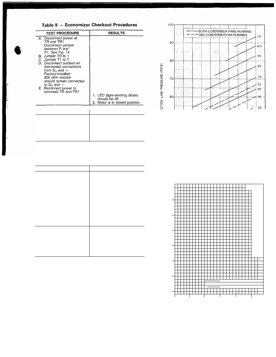
TO USE COOLING CHARGING CHART - Take out
door ambient temperature and read the suction pressure gage.
Refer to appropriate chart to determine correct suction tem
perature. If suction temperature is high, add refrigerant. If
suction temperature is low, carefully reclaim some of the
charge. Recheck suction pressure as charge is adjusted
Filter Drier — Replace whenever refrigerant system is
exposed to atmosphere.
30-
OUTDOOR TEMP
-
F
15
05
95
55
85
75
45
35
65
BOTH CONDENSER FANS RUNNING
LU Li_LLLL 1TJ__
-
ONE CONDENSER FAN RUNNING
20
30
40
SO
60
SUCTION LINE TEMPERATURE CF)
Fig. 24 — Cooling Charging Chart — 50HJ024
15