Evaporator fan, 50hj024 units – Carrier 50HJ015 User Manual
Page 13
Attention! The text in this document has been recognized automatically. To view the original document, you can use the "Original mode".
9.
10.
11
12
,
Rotate motor mount assembly back past original posi
tion toward evaporator coil.
Remove motor mounting nuts D and E (both sides).
Lift motor up through top of unit.
Reverse above procedure to reinstall motor.
Check and adjust belt tension as necessary.
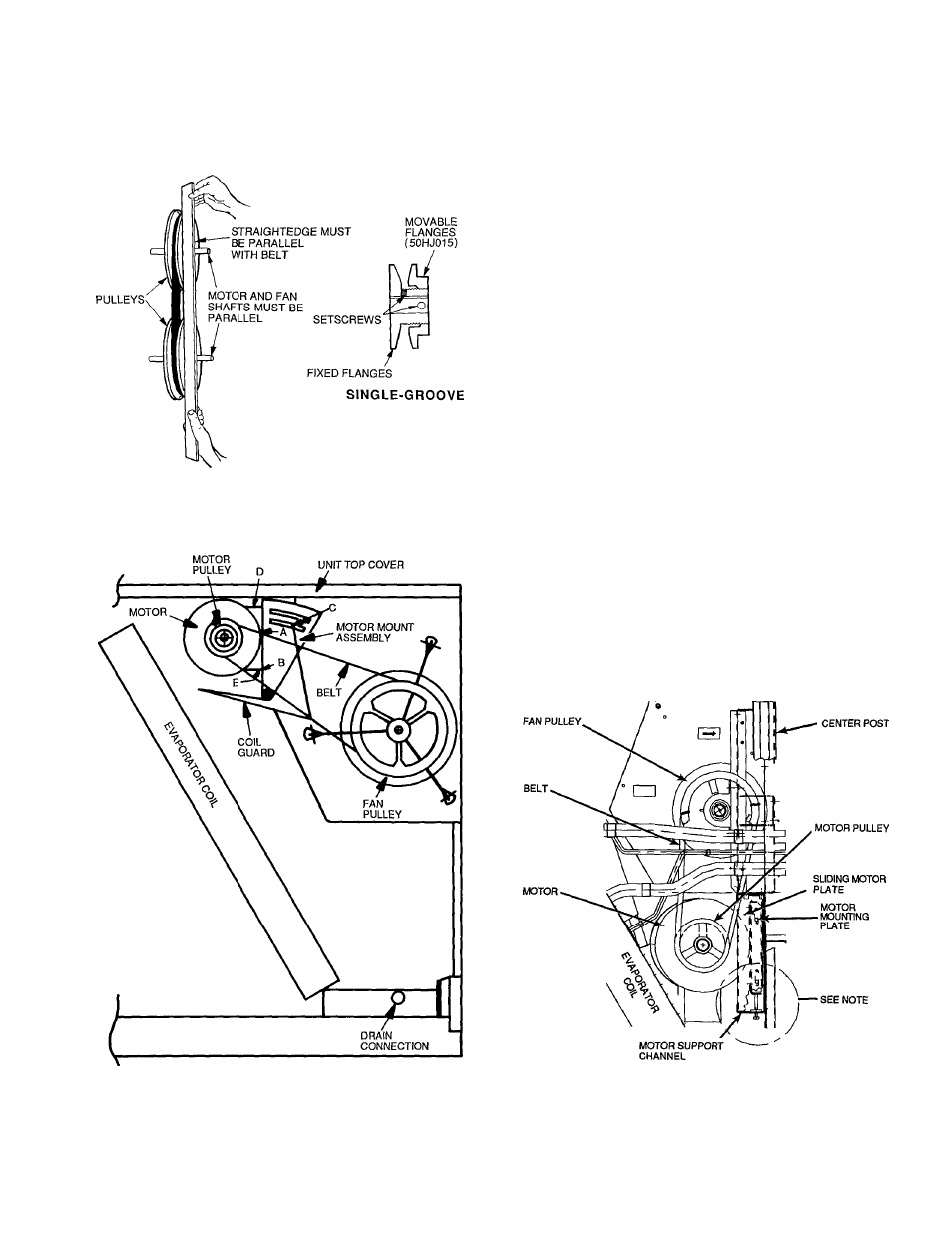
Fig. 19 — Evaporator-Fan Pulley Alignment
and Adjustment
Evaporator Fan, 50HJ024 Units
PERFORMANCE ADJUSTMENT - The 50HJ024 unit has
fixed pulleys. Fan speed can be adjusted (if necessary) only
by changing the pulley(s) and belt. See Table 8 for alter
nate drive selection.
To align fan and motor pulleys (see Fig. 19):
1. Loosen fan pulley setscrews.
2. Slide fan pulley along fan shaft.
3. Make angular alignment by loosening motor from mount
ing plate.
SERVICE AND REPLACEMENT (See Fig. 21) - The
50HJ024 unit uses a fan motor mounting system that fea
tures a slide-out motor mounting plate. To replace or serv
ice the motor, slide out the bracket.
1. Remove the evaporator-fan access panel and the heat
ing control access panel.
2. Remove the center post (located between the evapora
tor fan and heating control access panels) and all screws
securing it
3. Loosen nuts on the two carriage bolts in the motor mount
ing base.
Using jacking bolt under motor base, raise motor to
top of slide and remove belt. Secure motor in this po
sition by tightening the nuts on the carriage bolts.
Remove the belt drive.
6. Remove Jacking bolt and tapped jacking bolt plate.
7. Remove the 2 screws that secure the motor mounting
plate to the motor support channel.
8. Remove the 3 screws from the end of the motor sup
port channel that interfere with the motor slide path,
9 Slide out the motor and motor mounting plate,
10. Disconnect wiring connections and remove the 4 mount
ing bolts.
11. Remove the motor.
12. To install the new motor, reverse Steps 1-11.
4.
5.
Fig. 20 — 50HJ015 Evaporator-Fan Motor Section
NOTE; A 3V2-in, bolt and threaded plate are included in the instali-
er’s packet. They can be added to the motor support channel below
the motor mounting plate to aid in raising the motor.
Fig. 21 — 50HJ024 Evaporator-Fan Motor Section
13