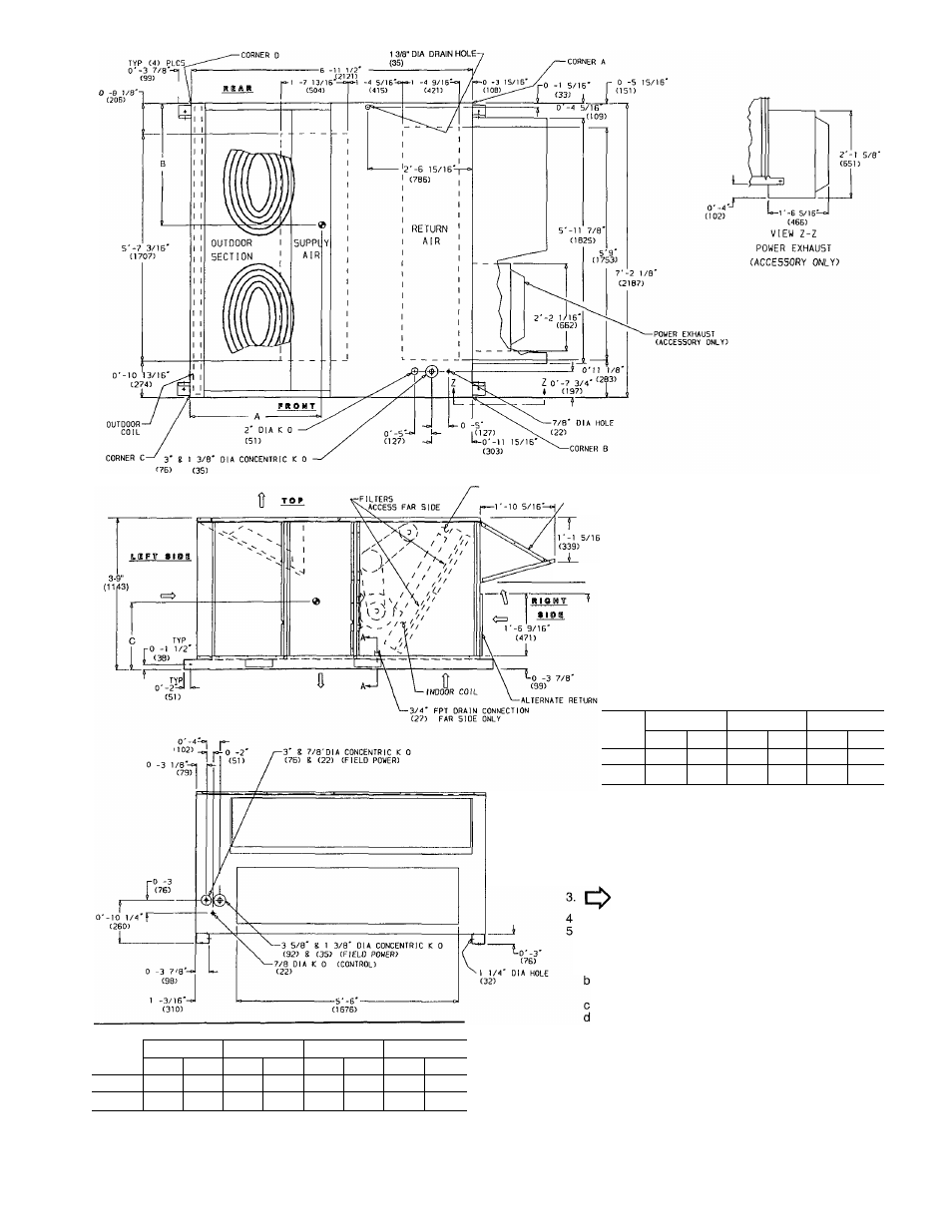
Fig. 4 — base unit dimensions – Carrier 50HJ015 User Manual
Page 4
Attention! The text in this document has been recognized automatically. To view the original document, you can use the "Original mode".
I
CONTROL BOX
ACCESS
•25% AIR On
''ECONOMIZER HOOD
pO -3 7/16'
i (87)
C
■ }
0’-3"
(76)
O'-l"
1
(102)
SECTION A-A
DIMENSIONS
UNIT
A
B
C
50HJ
Ft-in.
mm
Ft-in.
mm
Ft-in.
mm
015
3-0
914
2-9
838
1-10
559
024
3-4%
1035
3-7
1092
1-8
508
CORNER WEIGHT*
UNIT
50HJ
A
B
C
D
Lb
Kg
Lb
Kg
Lb
Kg
Lb
Kg
015
390
177
243
110
322
146
515
234
024
492
233
511
232
504
229
523
237
‘Weights are for unit only (with aluminum evaporator and condenser
coil fins) and do not include options or crating
LEGEND
KO
— Knockout
NOTES;
1 Dimensions in ( ) are in millimeters
2- ® Center of gravity.
Direction of airfloiw.
Ductwork to be attached to accessory roof curb only.
Minimum clearance:
a Rear; 7'-0" (2134) for coil removal. This dimension
can be reduced to 4'-0" (1219) if conditions permit
coil removal from the top
Left side: 4'-0" (1219) for proper condenser coil
airflow
Front' 4'-0" (1219) for control box access
Right side: 4'-0" (1219) for proper operation of damper
and power exhaust (if so equipped).
e. Top: 6'-0" (1829) to assure proper condenser fan
operation.
f. Local codes or jurisdiction may prevail.
With the exception of clearance for the condenser coil
and the damper/power exhaust as stated In note no 5, a
removable fence or barricade requires no clearance
Dimensions are from outside of corner post. Allow
O'-Vie" (8) on each side for top cover drip edge
i
Fig. 4 — Base Unit Dimensions