Step 6 — make electrical connections, Fig. 10 — field power wiring connections, Step 6 – Carrier 50HJ015 User Manual
Page 7: Make electrical connections
Attention! The text in this document has been recognized automatically. To view the original document, you can use the "Original mode".
Step 6 — Make Electrical Connections
FIELD POWER SUPPLY — Unit is factory wired for volt
age shown on nameplate.
When installing units, provide a disconnect, per NEC
(National Electrical Code) requirements, of adequate size
(Table 2).
All field wiring must comply with NEC and local
requirements.
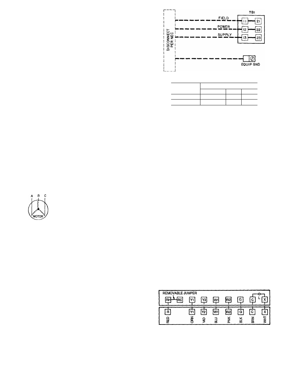
Route power lines through control box access panel or
unit basepan (Fig. 4) to connections as shown on unit wir
ing diagram and Fig. 10.
Transformer no. 1 is wired for 230-v unit. If 208/230-v
unit is to be run with 208-v power supply, the transformer
must be rewired as follows;
1. Remove cap from red (208 v) wire.
2. Remove cap from orange (230 v) spliced wire.
3. Replace orange wire with red wire
4. Recap both wires.
IMPORTANT; BE CERTAIN UNUSED WIRES
ARE CAPPED. Failure to do so may damage the
transformers.
Operating voltage to compressor must be within voltage
range indicated on unit nameplate. On 3-phase units, volt
ages between phases must be balanced within 2% and the
current must be balanced within 10%.
Use the following formula to determine the percentage of
voltage imbalance.
Percentage of Voltage Imbalance
— 100 X voltage deviation from average voltage
average voltage
Example; Supply voltage is 460-3-60.
AB =452 V
BC =464
V
AC =455
V
Average Voltage =
452 +464 +455
1371
“
3
= 457
Determine maximum deviation from average voltage.
(AB) 457 -452 =5 v
(BC) 464 -457 =7
V
(AC) 457 -455 =2 v
Maximum deviation is 7 v.
Determine the percentage of voltage imbalance;
7
Percentage of Voltage Imbalance = 100 x -
= 1.53%
This amount of phase imbalance is satisfactory as it is
below the maximum allowable 2%.
IMPORTANT; If the supply voltage phase imbal
ance is more than 2%, contact your local electric util
ity company immediately.
Unit failure as a result of operation on improper line volt
age or excessive phase imbalance constitutes abuse and may
cause damage to electrical components.
TB1 MAXIMUM WIRE SIZE
UNIT 50HJ
VOLTAGE
208/230
460
575
015
350 kcmil
2/0
2/0
024
350 kcmil
2/0
2/0
LEGEND
EQUIP
— Equipment
GND
— Ground
kcmil
— Thousand Circular Mils
NEC
— National Electrical Code
TB
— Terminal Block
Fig. 10 — Field Power Wiring Connections
FIELD CONTROL WIRING - Install a Carrier-approved
accessory thermostat assembly according to the installation
instructions included with the accessory. Locate thermostat
assembly on a solid wall in the conditioned space to sense
average temperature.
Route thermostat cable or equivalent single leads of
no. 18 AWG (American Wire Gage) colored wire from
subbase terminals through conduit in unit to low-voltage
connections as shown on unit label wiring diagram and in
Fig. 11.
NOTE; For wire runs up to 50 ft, use no. 18 AWG insu
lated wire (35 C minimum). For 50 to 75 ft, use no. 16
AWG insulated wire (35 C minimum). For over 75 ft, use
no. 14 AWG insulated wire (35 C minimum). All wire larger
than no. 18 AWG cannot be directly connected to the ther
mostat and will require a junction box and splice at the
thermostat.
Set heat anticipator settings as indicated in Table 3. Set
tings may be changed slightly to provide a greater degree of
comfort for a particular installation.
Refer to accessory remote control instructions as
required.
THERMOSTAT ASSEMBLY
Fig. 11 — Field Control Thermostat Wiring