Condenser-fan adjustment {fig. 22), Belt tension adjustment, Economizer adjustment – Carrier 50HJ015 User Manual
Page 14
Attention! The text in this document has been recognized automatically. To view the original document, you can use the "Original mode".
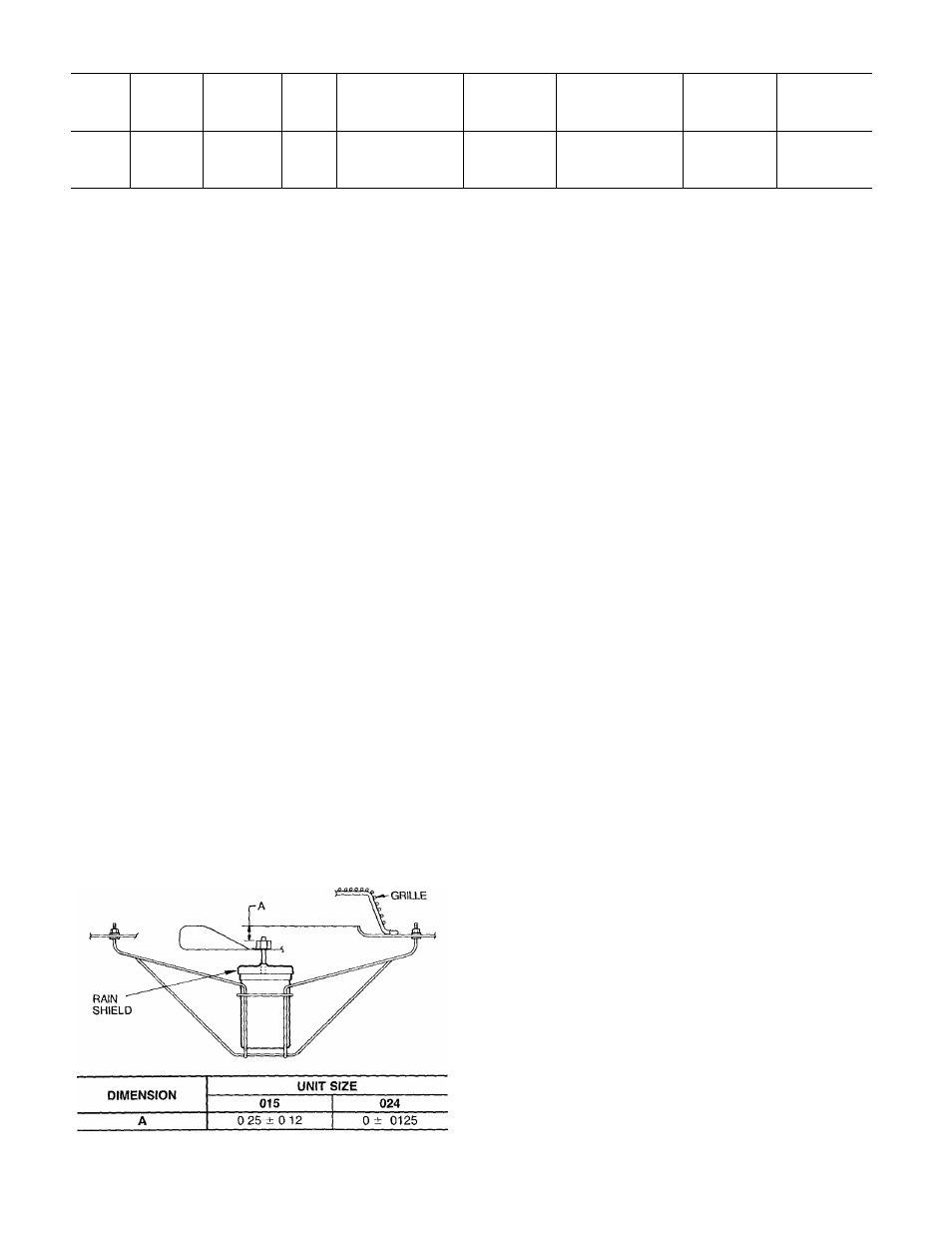
Table 8 — Alternate Drive Components Table, 50HJ024
UNIT
50HJ
MOTOR
HP
DRIVE
SOURCE
FAN
RPM
MOTOR
SHEAVE DATUM
DIMENSION*
(in.)
MOTOR
SHEAVE
PART NO.t
BLOWER
SHEAVE DATUM
DIMENSION*
(in.)
BLOWER
SHEAVE
PART NO.t
BELT
PART NO.t
7
V
2
Field
1181
5.6
BK62
8.4
BK90
BX50
024
71/2
Field
1244
5.9
BK65
8,4
BK90
BX51
Vh
Factory
1287
6 1
BK67
84
BK90
BX51
7'M
Field
1379
6.6
BK72
8.4
BK90
BX52
i
LEGEND
MPTA
— Mechanical Power Transmission Association
RMA
— Rubber Manufacturers’ Association
‘Datum dimension is equal to the old pitch diameter per RMA/MPTA
Standard IP20-1977. To convert to new pitch diameter per RMA/
Belt Tension Adjustment
— To adjust belt tension:
1. Loosen fan motor bolts.
2. a. 015 units:
Move motor mounting plate up or down for proper
belt tension ('/2 in, deflection with one finger),
b. 024 units;
Turn motor jacking bolt to move motor mounting plate
up or down for proper belt tension (Ys in. deflection
at midspan with one finger [9 lb force]).
3. Tighten nuts.
4. Adjust bolts and nut on mounting plate to secure motor
in fixed position.
Condenser-Fan Adjustment {Fig. 22)
1. Shut off unit power supply.
2. Remove fan top-grille assembly and loosen fan hub screws.
3. Adjust fan height on unit, using a straightedge placed
across the fan orifice.
4. Tighten setscrews and replace rubber hubcap to prevent
hub from rusting to motor shaft.
5. Fill hub recess with permagum if rubber hubcap is
missing.
Economizer Adjustment
— Refer to Tables 9 and
10 for economizer checkout procedures. Make certain the
outdoor-air damper is fully closed and the return-air damper
is fully open before completing the following steps.
1. Turn on power to the unit.
2. Turn the thermostat fan switch to the ON position. The
damper will go to the vent position.
3. Adjust the vent position with the minimum position ad
justment on the economizer control module. See
Fig. 14.
Fig. 22 — Condenser-Fan Adjustment
MPTA Standard IP20-1988, add 0.3 in. to the sheave datum
dimension.
tPart numbers for motor sheave, blower sheave, and belt are Brown
ing Catalog part numbers. The motor sheaves have Browning fixed
bore sheaves supplied with factory drive package.
4. Set the system selector switch to COOL position and
set the cooling temperature selector to its lowest
setting.
NOTE: The cooling mode may also be simulated by remov
ing the thermostat wires from terminals Y1 and Y2 and in
stalling a jumper between terminals R and Y1. Refer to unit
label diagram for terminal locations.
5. Set the outdoor-air thermostat (OAT) located in the econo
mizer section of the unit to 75 F.
6. If the outdoor temperature is below 75 F, the econo
mizer will control the mixed air with the mixed-air sen
sor. If the outdoor air is above 75 F, place a jumper
around the contacts of the OAT
7. Jumper terminal T to terminal T1 on the module (see
Fig. 14). The economizer will go to the full open
position. The outdoor-air damper will go to the full open
position, and the return-air damper will go to the full
closed position.
8. Adjust mechanical linkage, if necessary, for correct po
sitioning. It may be necessary to remove the filters to
adjust the linkage.
9. Remove the jumper from around the contacts of the
OAT if installed in Step 6. Remove the jumper from
terminals T and T1 installed in Step 7.
10. If the cooling mode was simulated to operate the unit
in Step 4, remove the jumper and reconnect the ther
mostat wires to terminals Y1 and Y2.
Power Failure — Dampers have a spring return In event
of power failure, dampers will return to fully closed posi
tion until power is restored. Do not manually operate damper
motor.
Refrigerant Charge — Amount of refrigerant charge
is listed on unit nameplate and in Table 1. Refer to Carrier
GTAC II; Module 5; Charging, Recovery, Recycling, and
Reclamation section for charging methods and procedures.
Unit panels must be in place when unit is operating dur
ing charging procedure.
NO CHARGE — Use standard evacuating techniques.
After evacuating system, weigh in the specified amount of
refrigerant (refer to Table 1).
LOW CHARGE COOLING - Using appropriate cooling
charging chart (see Fig. 23 and 24), add refrigerant until
conditions of the chart are met. Note that charging charts
are different from those normally used. Charts are based on
charging units to correct superheat for various operating con
ditions. An accurate pressure gage and temperature sensing
device are required. Connect temperature sensing device to
service port on suction line and insulate it so that outdoor
ambient temperature does not affect reading. Indoor-air cfm
must be within normal operating range of unit.
14