Carrier 542E User Manual
Page 8
Attention! The text in this document has been recognized automatically. To view the original document, you can use the "Original mode".
A80089
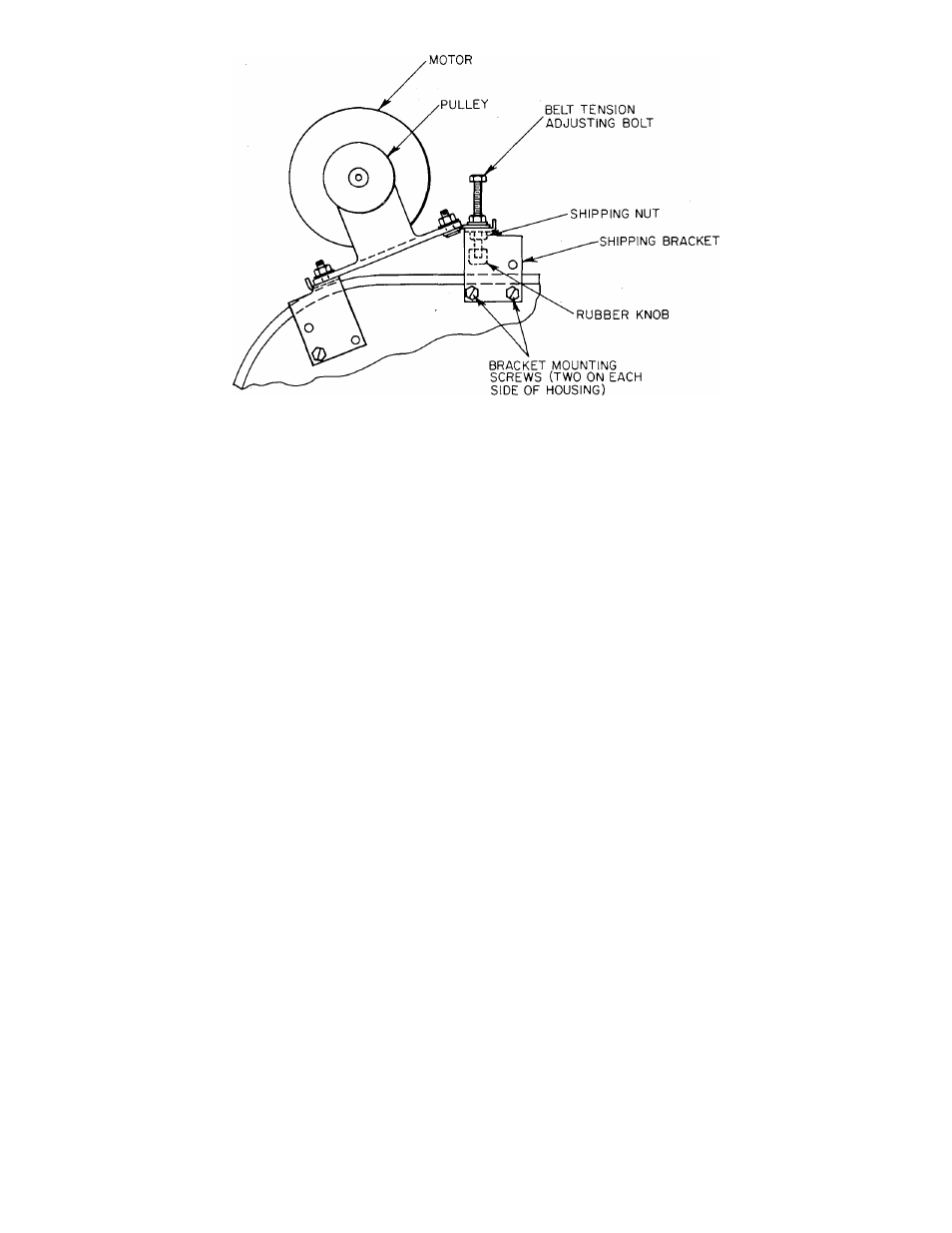
Figure 12—Removing Belt-Drive Blower Shipping Bracket
3. Read the following instructions on all WARNING,
CAUTION, and INFORMATION labels attached to
unit; for example, blower rotation labels, etc.
4. Refer to Figure 12 and remove shipping bracket from
belt-drive blower units as follows:
a.
Locate shipping bracket mounted on blower
housing.
b. Remove two bracket mounting screws from each
side of blower housing.
c. Remove rubber knob and shipping nut from adjust
ing bolt.
d. Discard shipping bracket and nut, then replace rub
ber knob on end of adjusting bolt.
e. See Section VI, part C, to adjust indoor airflow.
5. Make the following inspections:
a. Inspect for shipping and handling damages such as
broken lines, loose parts, disconnected wires, etc.
b. Inspect for oil at all refrigerant tubing connections
and on unit base. Detecting oil generally indicates a
refrigerant leak. Leak-test all refrigerant tubing
connections, using electronic leak detector, halide
torch, or liquid-soap solution. If refrigerant leak is
detected, see “Refrigerant Leaks” in the next part of
this section.
c. Inspect all field and factory wiring connections. Be
sure that connections are completed and tight.
d. Inspect coil fins. If damaged during shipping and
handling, carefully straighten fins with a fin comb.
6. Verify the following conditions:
a. Make sure that outdoor fan blade is correctly
positioned in fan orifice. Blades should clear motor
by H4
inch.
b. Make sure that air filter (s) is in place.
c. Make sure that condensate drain trap is filled with
water to ensure proper drainage.
d. Make sure that all tools and miscellaneous loose
parts have been removed.
7. Replace all access panels. (Unit is now ready for initial
startup.)
B. Refrigerant Leaks
Proceed as follows to repair a refrigerant leak and to charge
the unit:
WARNING: Never attempt to repair a soldered connection
while the refrigerant system is under pressure. Severe bodi
ly injury may result. Always wear protective goggles when
servicing the refrigerant system.
1. Locate leak and ensure that refrigerant system pressure
has been relieved.
2. Repair leak, following accepted practices.
NOTE: Install a filter-drier whenever the system has been
opened for repair.
3. Add a small charge of R-22 refrigerant to system and
leak-test unit.
4. Evacuate refrigerant system if additional leaks are not
found.
5. Charge unit with R-22 refrigerant, using a volumetric
charging cylinder or accurate scale. Refer to unit rating
plate for required charge. Be sure to add extra
refrigerant to compensate for the internal volume of the
filter-drier.
NOTE: See Section VI, part B, for checking and adjusting
refrigerant charge.
VI. STARTUP AND ADJUSTMENTS
CAUTION: Complete the required procedures given in
Sec
tion V, “Preparing Unit for Startup,” before starting the
unit.
Do not jumper any safety devices when operating the unit.
Do not operate the compressor until electric power has been
applied to the heat pump for a minimum of 4 hours to ensure
that the oif-cycle crankcase heater has sufficiently warmed
the compressor oil to free most of the accumulated
refrigerant.
Do not rapid-cycle the compressor. Allow 5 minutes between
“on” cycles to prevent compressor damage.
A. Checking Unit Operation
Start and check the unit for proper operation as follows:
1. Place room thermostat SYSTEM switch in OFF posi
tion. Observe that indoor blower motor starts when
FAN switch is placed in ON position and shuts down
when FAN switch is placed in AUTO position.
-8-