D. unit controls – Carrier 542E User Manual
Page 11
Attention! The text in this document has been recognized automatically. To view the original document, you can use the "Original mode".
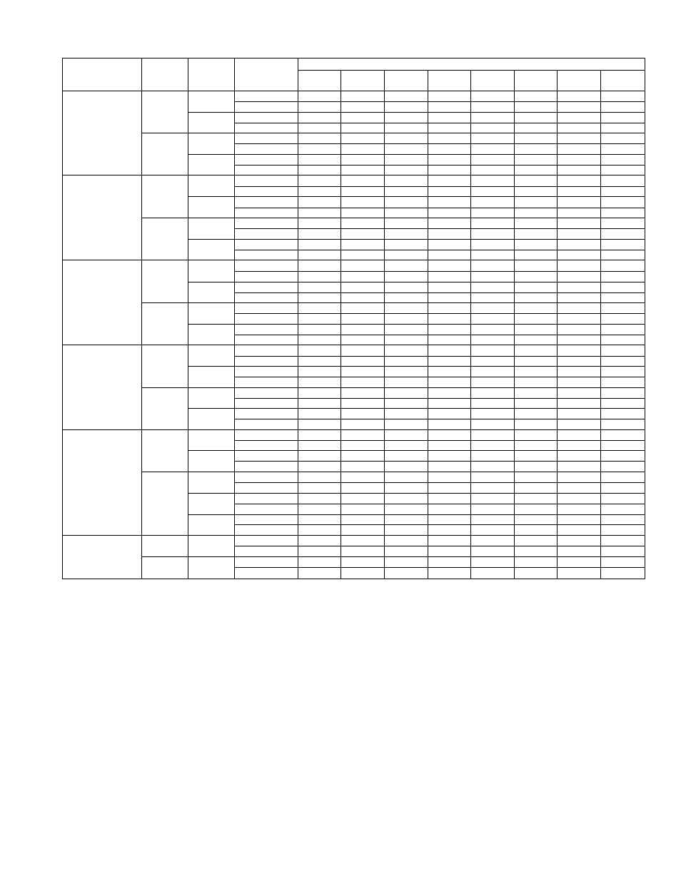
TABLE VI-AIR DELIVERY (FtVMin) AT INDICATED EXTERNAL STATIC PRESSURE & VOLTAGE*
Model
Blower
Motor
Speed
Opera
ting
Voltage
Applica-
tiont
External Static Pressure—Inches wc
0.0
0.1
0.2
0.3
0.4
0.5
0.6
0.7
542E024
Low
208
Heating
880
835
790
740
690
630
565
470
Cooling
850
810
770
725
675
615
550
465
230
Heating
965
925
880
835
780
720
655
575
Cooling
940
900
855
810
755
700
635
560
High
208
Heating
1015
970
920
870
815
750
685
605
Cooling
985
940
890
840
785
730
665
585
230
Heating
1070
1030
985
940
885
830
765
680
Cooling
1040
1000
955
910
855
800
735
660
542E030
Low
208
Heating
995
965
930
890
845
785
705
590
Cooling
980
945
910
865
820
760
680
560
230
Heating
1070
1050
1025
995
960
915
840
730
Cooling
1055
1030
1005
970
930
880
800
680
High
208
Heating
1165
■ 1145
1125
1095
1065
1020
955
845
Cooling
1150
1130
1105
1075
1035
980
900
770
230
Heating
1260
1245
1225
1200
1165
1125
1065
970
Cooling
1245
1225
1200
1170
1135
1080
1005
875
542E036
Low
208
Heating
1280
1235
1185
1135
1080
1020
955
875
Cooling
1225
1185
1140
1095
1040
985
920
850
230
Heating
1485
1435
1380
1325
1265
1200
1115
1025
Cooling
1400
1350
1300
1250
1190
1125
1050
970
High
208
Heating
1685
1630
1575
1510
1440
1360
1275
1160
Cooling
1565
1510
1455
1395
1325
1250
1160
1045
230
Heating
1850
1785
1720
1650
1575
1490
1395
1280
Cooling
1670
1615
1560
1495
1425
1345
1250
1100
542E042
Low
208
Heating
1400
1360
1315
M265v
1:205:
1130 :
1015-
_
Cooling
1370
1330
1280
1230
: 1165 : ■
1085
955
■
■
230
Heating
1655
1610
1560
1505
1435
1360
1270
: 1140
Cooling
1615
1565
1510
1450
1380
1305
1205
1050
High
208
Heating
1895
1840
1780
1715
1645
1570
1480
1365
Cooling
1825
1770
1710
1645
1570
1490
1395
1270
230
Heating
2125
2065
2005
1935
1860
1775
1685
1570
Cooling
2030
1970
1905
1835
1760
1675
1575
1440
542E048
Low
208
Heating
1690
1635
1575
1510
1440
1360
1270 :
1140
Cooling
1650
1595
1535
1475
1405
1325
1,230
1100
230
Heating
1905
1855
1800
1740
1675
1600
1510
:1370
Cooling
1860
1810
1755
1690
1625
1545
1445
1290
High
208
Heating
2005
1955
1900
1845
1780
1705
1625
1510
Cooling
1955
1905
1850
1790
1725
1650
1560
1430
230
Heating
2270
2195
2120
2040
1955
1870
1765
1650
Cooling
2180
2110
2040
1960
1880
1785
1685
1570
460
Heating
2070
2000
1925
1845
1760
1665
1560
1425
Cooling
2000
1930
1855
1775
1690
1595
1490
1355
542E060
(Single-
Low
230
Heating
2250
2205
2160
2110
2050
1990
1915
1830
Cooling
2180
2135
2085
2030
1970
1900
1815
1700
Phase
Units)
High
230
Heating
2700
2625
2550
2465
2380
2285
2175
2055
Cooling
2550
2475
2395
2315
2220
2120
2005
1860
* Deduct field-supplied air filter pressure drop & heater loss (when used) to obtain available external static pressure for ducting,
t Heating airflow values are with a dry coil. Cooling airflow values are with a wet coil.
NOTE:
Shaded portions of this table fall below 350ft^/min per 12,000 Btuh of rated cooling capacity. Indoor coil icing may ocur at airflows
below this point. Dashes are used in those areas of the table that fall beyond the capability of the indoor blower motor.
D. Unit Controls
All compressors have the following internal protection con
trols:
1. High-Pressure Relief VaZue—This valve opens when the
pressure differential between the low and high side
becomes excessive.
2. Compressor Ckterload—This internal overload interrupts
power to the compressor windings when either the cur
rent or internal temperature become excessive, and au
tomatically resets when the internal temperature drops
to a safe level. This overload may require up to 60
minutes (or longer) to reset; therefore if the internal
overload is suspected of being open, disconnect the
electrical power to the unit and check the circuit thru
the overload with an ohmmeter or continuity tester.
3. Low-Pressure Switch—This switch with automatic reset
interrupts the compressor control circuit when the
refrigerant high-side pressure becomes too low. It pro
tects the compressor from damage attributable to loss of
the refrigerant charge.
4. TimelTemperature Defrost System—The defrost control
system consists of a defrost timer, a defrost thermostat
switch, and a defrost relay. The system initiates defrost
cycle operation every 90 minutes if a coil icing condition
exists. See the defrost cycle sequence of operation in
Section VII.
5. Crankcase Heater—This device prevents overdilution of
compressor oil with refrigerant during shutdown
, periods, thereby extending the life of the compressor.
See the crankcase heater sequence of operation in Sec
tion VII.
6. Compressor Quick-Start Components—These components
are used with all single-phase units to improve com
pressor starting characteristics.
-
1 1
-