Table iv-heating performance pressures, Table v-cooling performance pressures – Carrier 542E User Manual
Page 9
Attention! The text in this document has been recognized automatically. To view the original document, you can use the "Original mode".
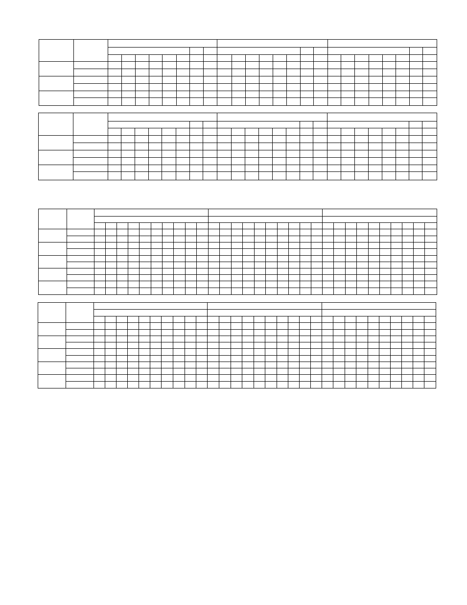
TABLE IV-HEATING PERFORMANCE PRESSURES
Air Temp at
Indoor Coil
Inlet |°F DB)
Pressure
Designation
(Psig)
54ZED24
542E030
542E036
Air Temperature at Outdoor Coil F°DB
Air Temperature at Outdoor Coii °FDB
Air Temperature at Outdoor Coil °FDB
60
50
40
30
20
10
0
-10
60
50
40
30
20
10
0
-10
60
50
40
30
20
10
0
-10
65
High Side
250
229
209
190
172
155
140
127
238
218
201
184
169
155
144
134
232
214
198
183
170
158
149
142
Low Side
69
59
49
41
33
25
18
14
71
60
50
41
32
24
18
13
64
52
46
38
31
25
18
13
70
High Side
268
243
220
199
180
162
147
134
251
231
211
195
179
165
153
142
247
230
213
198
184
171
161
152
Low Side
70
60
50
42
34
26
19
15
72
61
51
42
33
25
19
14
65
53
47
39
31
25
19
13
75
High Side
280
256
233
211
190
172
155
140
266
246
226
207
190
176
162
151
261
243
225
209
195
182
171
162
Low Side
71
61
51
43
35
27
20
16
73
62
52
43
34
26
20
15
66
54
48
40
32
26
19
14
Air Temp at
Indoor Coil
Inlet (°FDB|
Pressure
Designatiun
IPsig)
542E042
542E048
5420060. A 542E060
Air Temperature at Outdoor Coil °FDB
Air Temperature at Outdoor Coll "FOB
Air Temperature at Outdoor Coil °FDB
60
50
40
30
20
10
0
-10
60
50
40
30
20
10
0
-10
60
50
40
30
20
10
0
-10
65
High Side
254
234
216
193
171
159
148
136
262
237
214
193
174
158
144
134
268
238
210
186
166
151
142
136
Low Side
71
62
50
42
32
24
18
14
64
56
48
40
33
26
19
13
66
56
47
39
32
24
19
13
70
High Side
268
250
230
205
183
169
156
144
278
251
226
204
184
166
154
146
284
252
224
198
178
164
154
146
Low Side
72
63
51
43
33
25
18
14
65
57
49
41
34
27
20
13
67
57
48
40
32
25
19
13
75
High Side
283
266
243
218
194
180
166
153
290
266
242
220
201
184
169
158
298
268
238
212
190
1/4
162
156
Low Side
73
64
52
44
34
26
19
14
66
58
50
42
35
28
21
14
68
58
49
41
33
25
20
14
TABLE V-COOLING PERFORMANCE PRESSURES
Air Temp at
Indoor
Coil
Inlet (°FWB)
Pressure
Designation
IPsigI
542E024
542E030
54ZE035
Air Temp at Outdoor Coil |°F DB|
Air Temp at Outdoor Coil (°FDBI
Air Temp at Outdoor Coii l°F OBI
65
70
75
80
85
90
95
too
105
110
55
70
75
80
85
90
95
100
105
110
55
70
75
80
85
90
95
100
105
110
55
High Side
157 174 190 207 224 240 258 276 293 313 150 166 181 196 212 226 246 264 282 302 182 196 211 227 242 259 276 294 312 332
Low Side
58
59
60
61
62
63
64
66
67
68
60
62
63
65
67
69
71
73
75
77
67
69
70
72
74
75
76
78
79
81
60
High Side
162 179 195 212 228 244 261 279 296 315
153 169 185 200 216 230 250 268 286 306 185 199 215 231 246 263 280 298 316 336
Low Side
64
65
66
67
68
69
70
71
73
74
63
65
66
68
70
72
75
77
79
81
69
71
72
74
76
77
79
80
82
83
65
High Side
168 185 200 216 232 247 264 282 298 317
157 173 188 204 220 235 255 273 291 311 188 203 219 235 251 268 285 303 321 341
Low Side
70
71
72
73
75
76
77
78
79
80
67
69
70
72
74
76
79
81
83
85
71
73
74
76
78
80
81
83
85
86
70
High Side
173
191
206 223 239 253 270 288 304 324 160 177 192 208 224 240 259 277 295 315 192 207 223 239 255 273 290 308 326 346
Low Side
77
78
79
80
81
82
83
84
86
87
70
72
74
76
78
80
83
85
87
89
74
76
77
79
81
83
84
86
88
89
75
High Side
175 192 209 227 242 260 278 294 315 336 164 180 196 212 228 244 264 282 300 320 196 212 228 244 260 278 296 314 332 352
Low Side
84
85
86
87
88
90
91
93
94
95
74
76
78
80
82
84
87
89
91
93
79
81
83
84
86
88
89
91
93
9b
Air Temp at
Indoor
Coil
Inlet l°FWBI
Pressure
Oesignation
(Psig)
542E042
542E048
5420060 S 542E060
Air Temp at Outdoor Coil l°F 08)
Air Temp at Outdoor Coil l°F 08)
Air Temp at Outdoor Coil (°F0BI
55
70
75
80
85
90
95
100
105
110
65
70
75
80
85
90
95
100
105
110
65
70
75
80
85
90
95
100
105
110
55
High Side
165 179 192 206 222 237 254 270 289 308
178 192 207 224 238 255 272 291 308 330 176 189 202 217 233 249 266 283 300 320
Lew Side
60
62
63
65
67
68
70
72
74
75
61
62
63
65
66
68
70
72
74
76
59
61
62
63
65
6/
68
/0
/2
/4
60
High Side
169 183 196 210 226 241 258 275 293 312
183 197 212 229 243 260 277 296 314 335 180 193 207 222 237 254 270 287 305 324
Low Side
64
66
67
69
70
72
74
75
77
79
65
66
67
69
70
72
74
76
78
80
63
65
66
6/
68
/0
/1
/3
/5
n
65
High Side
173 187 201 215 231 246 263 280 298 317
188 203 218 235 249 266 283 302 320 340 185 198 212 227 242 259 275 292 31U 329
Low Side
68
69
71
73
74
76
78
79
81
83
69
70
71
73
74
76
78
80
82
84
67
69
70
/1
/2
/4
/5
/6
/8
80
70
High Side
177 191 205 220 235 251 268 285 303 322
193 208 223 240 254 271 288 307 326 345 191 205 219 234 250 266 283 301 319 338
Low Side
72
73
75
77
78
80
82
83
85
87
73
74
75
77
78
80
82
84
86
88
71
73
74
/5
I I
/9
80
81
83
85
75
High Side
181 196 210 225 240 256 273 290 308 327
198 214 229 246 260 277 294 312 332 350 198 212 227 242 258 274 292 310 328 346
Low Side
76
77
79
81
82
84
86
87
89
91
77
78
80
81
83
84
86
88
90
92
76
77
79
80
82
84
85
8/
89
91
2. Place SYSTEM switch in COOL position and FAN
switch in AUTO position. Set thermostat cooling control
below room temperature to start cooling cycle. Observe
that compressor, outdoor fan, and indoor blower motors
start. Observe that unit shuts down when control set
ting is satisfied. Wait 5 minutes for pressures to
equalize.
3. Place SYSTEM switch in HEAT position, and leave
FAN switch in AUTO position. Increase thermostat
heating control setting gradually until thermostat
“calls” for heat. Observe that compressor, outdoor fan,
and indoor blower motor start. If supplemental electric
heater is being used in the system, increase thermostat
heating control setting an additional 6 degrees. Observe
that the supplemental electric heater energizes. Set
control setting below room temperature, and observe
that heater deenergizes and that heat pump shuts down.
4. If supplemental electric heater is being used in the
system, leave FAN switch in AUTO position, SYSTEM
switch in HEAT position, and move emergency heat
switch from NORM, position to EM. HT. position. Set
thermostat control setting above room temperature to
start heating cycle. Observe that all supplemental
electric heat is energized, that indoor blower motor
starts, that emergency heat indicator bulb lights, and
that compressor and outdoor fan do not start. When con
trol setting is satisfied, observe that heater deenergizes
and that blower motor stops; however, indicator light
should remain on as long as emergency heat switch is in
EM. HT. position.
5.
If autochangeover thermostat P/N 34427DP115 is
being used, place both SYSTEM and FAN switches in
AUTO position. Observe that heat pump operates in
heating mode when heating control selector is set above
room temperature, and operates in cooling mode when
cooling control selector is set below room temperature.
B. Checking and Adjusting Refrigerant Charge
The refrigerant system is fully charged with R-22
refrigerant, tested, and factory-sealed. For most applica
tions, the factory charge is the correct amount for the best
performance; however, this charge rnay require a slight
adjustment to attain rated performance.
-
9
-