Carrier 542E User Manual
Page 7
Attention! The text in this document has been recognized automatically. To view the original document, you can use the "Original mode".
A79245
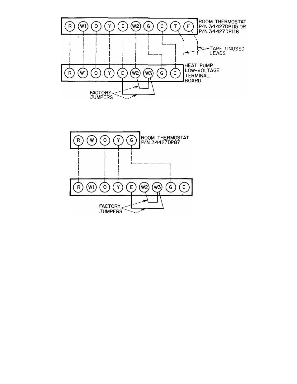
Figure 10—Field Low-Voltage Connections Using Room
Thermostat P/N 34427DP115 or P/N 34427DP118
HEAT PUMP
LOW-VOLTAGE
TERMINAL
BOARD
АГ9246
Figure 11—Field Low-Voltage Connections Using Room Thermostat P/N 34427DP87
board as shown in Figure 10 or 11, depending on which
recommended room thermostat is being used.
NOTE: When using thermostat P/N 34427DP115 or
34427DP118, run a thermostat lead from each of the 10
thermostat terminals. Insulate the end of the leads that do
not have a connection point in the unit.
D. Heat Anticipator Settings
The recommended room thermostats have a fixed heat antic
ipator for heat pump heating. When using an accessory-
electric heater to provide supplemental heat and emergency
heat capability for the system, see the Installation Instruc
tions packaged with the heater for setting the adjustable
second-stage heat anticipator.
V. PREPARING UNIT FOR STARTUP
WARNING/DANGER: A failure to observe the following
warnings could result in serious personal injury:
1. Follow recognized safety practices and wear protective
goggles when checking or servicing refrigerant system.
2. Do not operate compressor or provide any electric power
to unit unless compressor terminal cover is in place and
secured.
3. Do noT remove cdmpro.s.--or terminal cowr uniil all
elecrrical sources have bet ;n disconnec red.
4. Relieve all pressure from system before touching or dis
turbing anything inside terminal box if a refrigerant
leak is .suspected an)und
compressor
tcriViinal.s.
0. Do tiot use a torch to remove any coiitporienr. 8\-.41е7П
contains oil and refrigerant under pressure. To remove a
component, wear protective goggles and proceed as
follows:
a. 8hur oil' electrical ]io\ver t() unit.
b. Relieve all pre.s.suri' t'roui .system.
c. Cut component connecting tubing with tubing cut
ter and remove component from unit.
d. Carefully unsweat remaining tubing stubs when
necessary. Oil can ignite when exposed to torch
flame.
A. Prestartup Procedures
Proceed as follows to inspect and prepare the unit for initial
startup:
1. Remove all access panels.
2. Remove stryofoam shipping blocks from between com
pressor and divider panel, and between accumulator and
divider panel
-
7
-