Carrier 542E User Manual
Page 4
Attention! The text in this document has been recognized automatically. To view the original document, you can use the "Original mode".
USE SPREADER BARS TO PROTECT UNIT
USE SPREADER BARS TO PROTECT UNIT
A79148
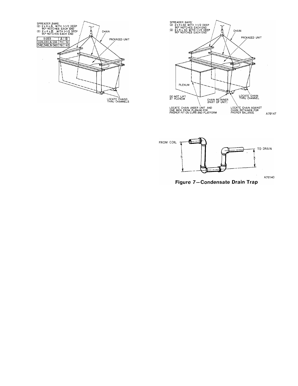
Figure 5—542E Suggested Rigging
I. MOVING AND SETTING UNIT IN PLACE
CAUTION: Use spreader bars when rigging the unit to be
lifted to protect the top and sides. Model 542E must be
rigged for lifting as shown in Figure 5. Model 542D must be
rigged for lifting as shown in Figure 6. Use extreme caution
to prevent damage when moving the unit. It must remain in
an upright position during all rigging and moving opera
tions. The unit must be level for proper condensate
drainage; therefore, the ground-level pad or accessory roof
mounting curb must be level before setting the unit in place.
When a field-fabricated support is used instead of the ac
cessory curb, ensure that the support is level and properly
supports the unit and plenum.
When selecting an installation site, locate the unit on the
side opposite the prevailing wind to assure proper operation
of the defrost cycle and to avoid snow drifts that could block
the outdoor coil. Be sure that the unit is installed at least 6
inches above the highest probable snow level to prevent block
age of the outdoor coil and to assure proper drainage of de
frosted ice.
A. Rooftop Installation
CAUTION: When installing the unit on a rooftop, be sure
that the roof will support the additional weight. Refer to the
Product Data Sheet (PDS) for Models 542D and 542E to
obtain total weight and corner weight information.
When installing a Model 542D Downflow Unit or a Model
542E End-discharge Unit with an accessory downflow
plenum, the accessory roof-mounting curb must be installed
on, and flashed into, the roof before unit installation. The
instructions for installing the curb are packaged with the
curb.
When installing a Model 542E without downflow plenum,
place the unit on a level base that provides proper support.
On flat roofs, be sure that the unit is located at least 4 inches
above the highest expected water level on the roof to prevent
flooding. Consult local codes for additional installation
requirements.
B. Ground-Level Installation
Place the unit on a solid, level concrete pad that is a
minimum of 4 inches thick and that extends approximately
2 inches beyond the casing on all four sides of the unit. Do
not secure the unit to the pad except when required by local
codes.
C. Clearances
The required minimum operating and service clearances are
shown in Figures 3 and 4. (Refer to the 542D clearances
when installing Model 542E with an accessory downflow
plenum.)
Figure 6—542D060 Suggested Rigging
CAUTION: Do not restrict outdoor airflow. An air restric
tion at either the outdoor-air inlet (the entire surface of the
outdoor coil) or the fan discharge can be detrimental to com
pressor life.
The outdoor fan discharges through the top of the unit.
Ensure that the fan discharge does not recirculate to the
outdoor coil. Do not locate the unit in either a corner or
under a complete overhead obstruction. The minimum
clearance under a partial overhang (such as a normal house
roof overhang) is 48 inches.
Do not locate the unit where water, ice, or snow from an
overhang or roof will damage or flood the unit by falling on
the top. Do not locate the unit where grass, shrubs, or other
plants will interfere with the airflow either into or out of the
unit.
II. CONDENSATE AND DEFROST DISPOSAL
NOTE: Ensure that defrost and condensate water disposal
methods comply with local codes, restrictions, and practices.
Models 542D and 542E dispose of condensate water through
a 3/4-inch MPT plastic drain fitting. To prevent damage dur
ing the shipping and moving of the unit, this fitting and a
plastic drain pipe are shipped inside the unit compressor
compartment (secured with tape). Locate this fitting and
'nsert the nonthreaded end into the plastic drain pipe. See
Figure 8. Insert the plastic pipe over the drain on the drain
pan. The pipe and fitting must lay flat against the base for
proper drainage. The residual curvature in the pipe must be
in a horizontal plane.
Install a 3-inch trap at the drain fitting to ensure proper
drainage. See Figure 7. Make sxire that the outlet of the trap
is at least 2 inches lower than the unit drain pan connection
to prevent the pan from overflowing. Prime the trap with
water.
-
4
-