Table 6 — fan cycling control, Ieaving-waier, Leaving mtsr oesigii – Carrier 30GA User Manual
Page 9
Attention! The text in this document has been recognized automatically. To view the original document, you can use the "Original mode".
pressure in Table 5. Close condenser fan circuit
breaker. After pressure drops to cut-in setting, reset
the control circuit by opening and then closing the
control circuit switch. After control circuit is reset,
the Time Guard® timer will cycle and in approxi
mately 5.5 minutes the compressor will restart.
Low-Pressure Switch
has fixed, nonadjustable set
tings. The switch is mounted on the suction line.
TO CHECK — Slowly close liquid shutoff valve and
allow compressor to pump down. Compressor
should shut down when suction pressure drops to
cutout pressure in Table 5, and should restart when
pressure builds up to cut-in pressure shown.
Table 5 — Pressure Switch Settings (psig)
UNIT
30GA
020,025,030
Winter Start Control
— Switch “D” in the 4-
function timer bypasses low-pressure switch for
2-1/2 minutes on unit start-up.
Head Pressure Control
reduces condensing capac
ity under low ambient conditions.
FAN CYCLING — These 30GA units have stand
ard provision for fully automatic intermediate-
season head pressure control thru condenser fan
cycling. Fan No. 2 is cycled by a pressure con
troller which responds to variation in discharge
pressure. The pressure sensor is located in the
liquid line of the refrigerant circuit. Fan No. 3
cycling is controlled by outdoor air temperature.
The temperature switch is located in the lower
right comer of the rear panel of the compressor
compartment, below the condenser coil (see Fig. 4).
Thru a hole in the panel, the sensing element is ex
posed to air entering the No. 1 fan compartment.
Fan No. 1 is non-cycling. Table 6 shows the oper
ating settings of the pressure and temperature
controllers.
troller is factory set to control from return water
temperature thm a cooling range of 10 F. The
sequence switches are factory calibrated and sealed
and should not require any field changes. Table 7
shows the factory-set temperature steps for the 2-
and 3-step controllers.
IMPORTANT: if a dilTerent retum-\yaier cool
ing range a
ieaving-waier
control is specified,
or if htine is to be used,^ the coniroBer must be
changed. Consult local Carrier representative
for proper co.ntrc4 device.
Table 7 — Capacity Control Steps
UNIT
30GA
HIGH PRESSURE
LOW PRESSURE
020
Cutout
Cut-in
Cutout
Cut-In
.... .
...
*■
60 ^ 0
025,
374 +5
274 ±5
27 +4
030
CONTROL
%
OPER T TEMP
STEPS
CAP.
CYL
Cut-in
Cutout
T'
” ”2 '
”441
2
100
4
527,
50
1
33
46
V
2
44 f
2
67
4
50
47V2
3
100
6
53V2
51
‘Return
chilled
water
temperature
|-Design set point
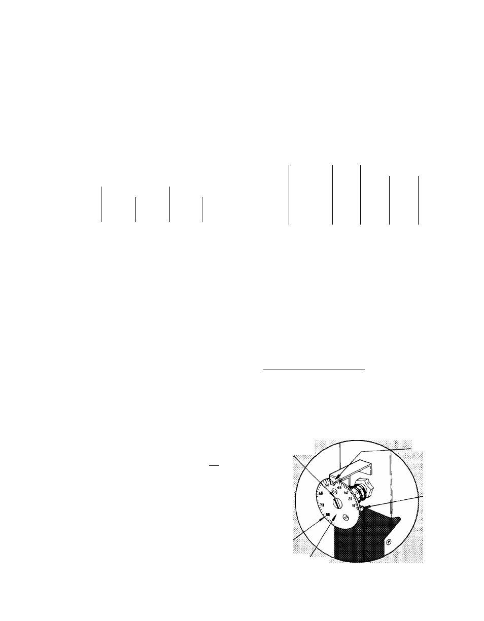
The return water temperature at which the last
step of capacity unloads is indicated by the leaving
water temperature design set point on the adjust
able dial (Fig. 8). Example; design set point is at
44 F. On a reduction in load, the capacity of the
unit is reduced to zero when return water tempera
ture drops to 44 F.
WARNING; Any alteration of factory settings,
except de.sign set point, without Carrier author
ization, may void the Carrier Warranty'.
Design Set Point Adjustment — When unit is ready
for operation, insert small screwdriver in adjusting
slot (Fig. 8) and rotate to turn dial (the dial may
be turned by hand if desired).
Rotate until the design set point for the installa
tion appears directly under the pointer. Insert a
thermometer in the return chilled water connec-
Table 6 — Fan Cycling Control
CONTROL BY
Temp (±3 F)
Pressure (±5)
SWITCH OPENS
70
1 óÒ psig
SWITCH CLOSES
80
2óÒ psig
Capacity Control System
consists of a multiple-
step water temperature controller, electric cylinder
bank unloader(s) and 2 separately controlled refrig
erant circuits (liquid-line solenoid valves). A hot
gas bypass arrangement on the final step of unload
ing is factory supplied.
MULTIPLE-STEP CONTROLLER - Consists of
load switches actuated by pressures developed in a
temperature-sensing bulb located in the return
water line of the chilled water system. The con-
AOiSLiSTiÌÌG
SLO'
POttiTER
STOA
LEAViNG
mTSR
OESiGii
SET-
CALiSRATSO
Fig. 8 — Set Point Adjustment