Cd [i, 3 qp – Carrier 30GA User Manual
Page 4
Attention! The text in this document has been recognized automatically. To view the original document, you can use the "Original mode".
IMPORTANT: Make provisi-on for the auxii-
iaxy power to be always on (except for servic-
mg or prolonged shutdown) to ensure power
to the heaters.
A toggle switch (marked SW) in the control box
allows the control circuit to be manually discon
nected when necessary. This switch does not
affect the crankcase heater, cooler heater cable
or convenience outlet.
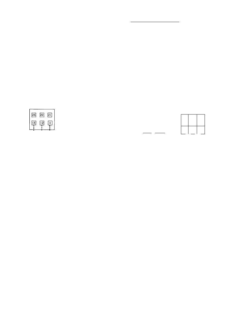
3. Control Circuit Interlocks — A flow switch
should be installed in the chilled water line to
prevent the unit from running when water is not
circulating thru the cooler. This switch (no.
HR81LG005) is available as an accessory from
the Syracuse parts center, or equivalent can be
field purchased. Also, auxiliary contacts for the
chilled water pump starter should be installed in
the control circuit as additional protection
against unit operation when pump is not run
ning. Both of these items should be electrically
interlocked in the control circuit, between
terminals [T] and [2 on TBS. See Fig. 3 for field
wiring.
UNIT CONTROL BOX
A-
SW
T8 I
CD [I]
TB4
REMOVE RED WIRE BETWEEN Q] AND
TBS
TB3
EQUIP GND
(Z)—1
TB2
L3 L2 LI
FIELD POWER SUPPLY
m
EQUIP
GND
L_
[T]
I
I
(AUX)'--
-|cWFsh'*~'ICWPsM
3 qp
LI
L2
CONTROL CIRCUIT
INTERLOCKS (ACCESS)
AUXILIARY
POWER SUPPLY
r+-
DISCONNECT PER NEC
LEGEND
CWFS — Chilled Water Flow Switch
CWPS — Chilled Water Pump Starter Auxiliary Contacts
SW
— On.Off Switch, Control Circuit
TB
— Terminal Board
___Field Control Wiring
—
Field
Power
Wiring
_ Factory Wiring
Fig. 3 — Field Wiring Connections
START-UP AND SERVICE
Initial Check
— Do not attempt to start the liquid
chiller, even momentarily, until the following steps
have been completed.
1. Check all auxiliary components such as chilled
liquid circulating pump, air handling equip
ment, or other equipment to which the chiller
supplies liquid. Consult the manufacturer’s
instructions. Pump auxiliary contactor and
flow switch interlocks must be properly in
stalled (see Fig. 3, Field Wiring Connections).
2. Check chilled water safety thermostat. (See
Safety Thermostat for adjustment.)
3. Backseat (open) compressor suction and dis
charge shutoff valves. Close valves one turn to
allow pressure to reach test gages.
4. Open liquid line valve.
5. Fill chilled liquid circuit with clean water or
other noncorrosive fluids to be cooled. Bleed
all air out of high points of system.
6. Set temperature controller (see Multiple-Step
Controller).
7. Check tightness of all electrical connections.
8. Compressor oil should be visible in bull’s-eye
(see Oil Charge).
9. Be sure there are no refrigerant leaks (see Leak
Test and Dehydration).
10. Be sure unit is fully charged with refrigerant
(see Refrigerant Charge).
11. Electrical power source must agree with name
plate rating.
12. Temperature sensor of fan cycling control must
be unobstructed (see Fan Cycling).
13. Crankcase heater must be firmly locked into
compressor crankcase. Be sure crankcase is
warm (heater should be on for 24 hours before
starting compressor).
14. Be sure compressor floats freely on the mount
ing springs. See Compressor Mounting section
and Fig. 2 for installation of loose washers and
snubbers.
Leak Test and Dehydration
— All 30GA units are
shipped with complete operating charge of Refrig
erant 22 (Table 1) and should be under sufficient
pressure to conduct leak test after installation. If
there is no system pressure, admit refrigerant until
a pressure is observed and then proceed to test for